Article Paths
From News: HOME › NEWS › Global Flange Standards
The Unabridged Archive Index
The Digital Archive of Global Flange Standards
This digital archive is the definitive, unabridged transcription of global flange standards, executed under a mandate for absolute completeness ("Protocol Zero"). Its purpose is to eliminate data omission and sampling errors common in simplified charts. The tables below are exhaustive, containing every standard size as defined within official documentation. This resource is intentionally data-dense and comprehensive, designed for professional engineers, designers, and standards archivists who require definitive data.
The Core Guide to Butterfly Valve & Flange Connection
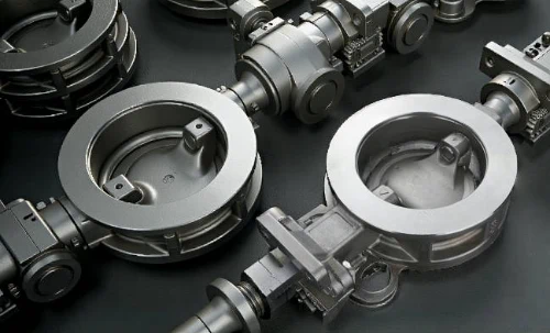
This archive contains data for standard pipeline flanges (e.g., EN 1092-1, ASME B16.5). Butterfly valves are designed to be installed into piping systems that use these exact standards. There is no separate "butterfly valve flange standard." Understanding this relationship is critical for correct valve selection and installation.
⊙ Key Connection Types & Their Relation to Flange Standards:
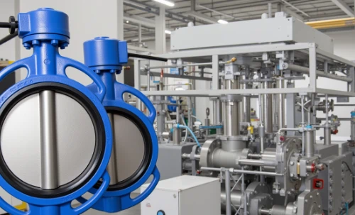
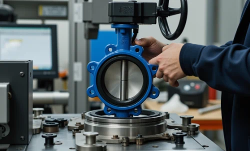
- Wafer Type: The valve body is clamped between two pipeline flanges. The flange data in this archive (PCD, bolt quantity, bolt size) is essential to ensure the clamping bolts can pass through the valve's bolt holes correctly.
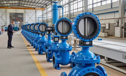
- Lug Type: The valve body has threaded "lugs" (holes) that align perfectly with the bolt pattern of a standard flange. This allows the valve to be bolted directly to one flange, which is useful for end-of-line service. The dimensional data herein is the blueprint for the lug positioning on the valve.
- Double Flanged Type: The valve has two integral flanges as part of its body. The dimensions of these valve flanges must be identical to the pipeline flange standard (e.g., EN 1092-1 PN16) for a direct, bolted connection.
⊙ CRITICAL ENGINEERING CHECK - DISC INTERFERENCE: Always verify that the butterfly valve disc, when fully opened, does not interfere with the bore of the connecting pipe or the flange itself. This is particularly important with smaller nominal sizes, thicker-walled pipes (higher schedules), or when installing valves adjacent to other fittings. Key valve standards like EN 593 and API 609 define the compatibility requirements between valves and these pipeline flange standards.
The Unabridged Standards Data
Below are the complete, individual data tables for each standard and pressure class, transcribed without omission. Use the index above for rapid navigation.
ASME / ANSI (American)
The American Society of Mechanical Engineers (ASME) B16 standards are the cornerstone for North American piping systems and are widely used globally.
ASME B16.5 - Class 150
| NPS (in) |
DN (mm) |
OD (mm) |
PCD (mm) |
No. Bolts |
Bolt Size (in) |
| 1/2 |
15 |
88.9 |
60.5 |
4 |
1/2 |
| 3/4 |
20 |
98.6 |
69.9 |
4 |
1/2 |
| 1 |
25 |
108.0 |
79.2 |
4 |
1/2 |
| 1 1/4 |
32 |
117.6 |
88.9 |
4 |
1/2 |
| 1 1/2 |
40 |
127.0 |
98.6 |
4 |
1/2 |
| 2 |
50 |
152.4 |
120.7 |
4 |
5/8 |
| 2 1/2 |
65 |
177.8 |
139.7 |
4 |
5/8 |
| 3 |
80 |
190.5 |
152.4 |
4 |
5/8 |
| 3 1/2 |
90 |
215.9 |
177.8 |
8 |
5/8 |
| 4 |
100 |
228.6 |
190.5 |
8 |
5/8 |
| 5 |
125 |
254.0 |
215.9 |
8 |
3/4 |
| 6 |
150 |
279.4 |
241.3 |
8 |
3/4 |
| 8 |
200 |
342.9 |
298.5 |
8 |
3/4 |
| 10 |
250 |
406.4 |
362.0 |
12 |
7/8 |
| 12 |
300 |
482.6 |
431.8 |
12 |
7/8 |
| 14 |
350 |
533.4 |
476.3 |
12 |
1 |
| 16 |
400 |
596.9 |
539.8 |
16 |
1 |
| 18 |
450 |
635.0 |
577.9 |
16 |
1 1/8 |
| 20 |
500 |
698.5 |
635.0 |
20 |
1 1/8 |
| 22 |
550 |
749.3 |
685.8 |
20 |
1 1/4 |
| 24 |
600 |
812.8 |
749.3 |
20 |
1 1/4 |
ASME B16.5 - Class 300
| NPS (in) |
DN (mm) |
OD (mm) |
PCD (mm) |
No. Bolts |
Bolt Size (in) |
| 1/2 |
15 |
95.3 |
66.5 |
4 |
1/2 |
| 3/4 |
20 |
117.3 |
82.6 |
4 |
5/8 |
| 1 |
25 |
124.0 |
88.9 |
4 |
5/8 |
| 1 1/4 |
32 |
133.4 |
98.6 |
4 |
5/8 |
| 1 1/2 |
40 |
155.4 |
114.3 |
4 |
3/4 |
| 2 |
50 |
165.1 |
127.0 |
8 |
5/8 |
| 2 1/2 |
65 |
190.5 |
149.4 |
8 |
3/4 |
| 3 |
80 |
209.6 |
168.1 |
8 |
3/4 |
| 3 1/2 |
90 |
228.6 |
184.2 |
8 |
3/4 |
| 4 |
100 |
254.0 |
200.2 |
8 |
3/4 |
| 5 |
125 |
279.4 |
235.0 |
8 |
7/8 |
| 6 |
150 |
317.5 |
269.7 |
12 |
7/8 |
| 8 |
200 |
381.0 |
330.2 |
12 |
1 |
| 10 |
250 |
444.5 |
387.4 |
16 |
1 1/8 |
| 12 |
300 |
520.7 |
450.9 |
16 |
1 1/4 |
| 14 |
350 |
584.2 |
514.4 |
20 |
1 1/4 |
| 16 |
400 |
647.7 |
571.5 |
20 |
1 3/8 |
| 18 |
450 |
711.2 |
628.7 |
24 |
1 3/8 |
| 20 |
500 |
774.7 |
685.8 |
24 |
1 3/8 |
| 22 |
550 |
838.2 |
742.9 |
24 |
1 1/2 |
| 24 |
600 |
914.4 |
812.8 |
24 |
1 5/8 |
ASME B16.5 - Class 600
| NPS (in) |
DN (mm) |
OD (mm) |
PCD (mm) |
No. Bolts |
Bolt Size (in) |
| 1/2 |
15 |
95.3 |
66.5 |
4 |
1/2 |
| 3/4 |
20 |
117.3 |
82.6 |
4 |
5/8 |
| 1 |
25 |
124.0 |
88.9 |
4 |
5/8 |
| 1 1/4 |
32 |
133.4 |
98.6 |
4 |
5/8 |
| 1 1/2 |
40 |
155.4 |
114.3 |
4 |
3/4 |
| 2 |
50 |
165.1 |
127.0 |
8 |
5/8 |
| 2 1/2 |
65 |
190.5 |
149.4 |
8 |
3/4 |
| 3 |
80 |
209.6 |
168.1 |
8 |
3/4 |
| 3 1/2 |
90 |
228.6 |
184.2 |
8 |
7/8 |
| 4 |
100 |
273.1 |
215.9 |
8 |
7/8 |
| 5 |
125 |
330.2 |
266.7 |
8 |
1 |
| 6 |
150 |
355.6 |
292.1 |
12 |
1 |
| 8 |
200 |
419.1 |
349.3 |
12 |
1 1/8 |
| 10 |
250 |
508.0 |
431.8 |
16 |
1 1/4 |
| 12 |
300 |
558.8 |
489.0 |
20 |
1 1/4 |
| 14 |
350 |
603.3 |
527.1 |
20 |
1 3/8 |
| 16 |
400 |
685.8 |
596.9 |
20 |
1 1/2 |
| 18 |
450 |
749.3 |
654.1 |
20 |
1 5/8 |
| 20 |
500 |
812.8 |
711.2 |
24 |
1 5/8 |
| 22 |
550 |
876.3 |
768.4 |
24 |
1 3/4 |
| 24 |
600 |
939.8 |
825.5 |
24 |
1 7/8 |
ASME B16.5 - Class 900
| NPS (in) |
DN (mm) |
OD (mm) |
PCD (mm) |
No. Bolts |
Bolt Size (in) |
| 1/2 |
15 |
120.7 |
82.6 |
4 |
3/4 |
| 3/4 |
20 |
130.3 |
92.2 |
4 |
3/4 |
| 1 |
25 |
139.7 |
98.6 |
4 |
3/4 |
| 1 1/4 |
32 |
158.8 |
111.0 |
4 |
7/8 |
| 1 1/2 |
40 |
177.8 |
127.0 |
4 |
1 |
| 2 |
50 |
215.9 |
158.8 |
8 |
7/8 |
| 2 1/2 |
65 |
247.7 |
184.2 |
8 |
1 |
| 3 |
80 |
266.7 |
200.2 |
8 |
1 1/8 |
| 4 |
100 |
304.8 |
235.0 |
8 |
1 1/4 |
| 5 |
125 |
368.3 |
292.1 |
8 |
1 3/8 |
| 6 |
150 |
393.7 |
317.5 |
12 |
1 3/8 |
| 8 |
200 |
469.9 |
381.0 |
12 |
1 1/2 |
| 10 |
250 |
558.8 |
463.6 |
12 |
1 3/4 |
| 12 |
300 |
622.3 |
520.7 |
16 |
1 3/4 |
| 14 |
350 |
685.8 |
584.2 |
16 |
2 |
| 16 |
400 |
762.0 |
660.4 |
16 |
2 1/4 |
| 18 |
450 |
831.9 |
717.6 |
16 |
2 1/2 |
| 20 |
500 |
889.0 |
774.7 |
20 |
2 1/2 |
| 24 |
600 |
1066.8 |
939.8 |
20 |
3 |
ASME B16.47 Series A
| NPS (in) |
DN (mm) |
OD (mm) |
PCD (mm) |
No. Bolts |
Bolt Size (in) |
| 26 |
650 |
870.0 |
793.8 |
24 |
1 1/4 |
| 28 |
700 |
933.5 |
857.3 |
28 |
1 1/4 |
| 30 |
750 |
997.0 |
914.4 |
28 |
1 3/8 |
| 32 |
800 |
1060.5 |
977.9 |
28 |
1 1/2 |
| 34 |
850 |
1124.0 |
1035.1 |
32 |
1 1/2 |
| 36 |
900 |
1187.5 |
1092.2 |
32 |
1 5/8 |
| 38 |
950 |
1257.3 |
1162.1 |
32 |
1 3/4 |
| 40 |
1000 |
1320.8 |
1225.6 |
36 |
1 3/4 |
| 42 |
1050 |
1384.3 |
1282.7 |
36 |
1 7/8 |
| 44 |
1100 |
1447.8 |
1346.2 |
40 |
1 7/8 |
| 46 |
1150 |
1517.7 |
1416.1 |
40 |
2 |
| 48 |
1200 |
1581.2 |
1473.2 |
44 |
2 |
| 50 |
1250 |
1651.0 |
1543.1 |
44 |
2 1/4 |
| 52 |
1300 |
1714.5 |
1600.2 |
48 |
2 1/4 |
| 54 |
1350 |
1784.4 |
1670.1 |
48 |
2 1/2 |
| 56 |
1400 |
1847.9 |
1733.6 |
52 |
2 1/2 |
| 58 |
1450 |
1917.7 |
1803.4 |
52 |
2 3/4 |
| 60 |
1500 |
1981.2 |
1860.6 |
56 |
2 3/4 |
ASME B16.47 Series B
| NPS (in) |
DN (mm) |
OD (mm) |
PCD (mm) |
No. Bolts |
Bolt Size (in) |
| 26 |
650 |
825.5 |
774.7 |
24 |
1 1/8 |
| 28 |
700 |
882.7 |
828.7 |
28 |
1 1/8 |
| 30 |
750 |
946.2 |
889.0 |
28 |
1 1/4 |
| 32 |
800 |
1003.3 |
946.2 |
32 |
1 1/4 |
| 34 |
850 |
1054.1 |
997.0 |
32 |
1 1/4 |
| 36 |
900 |
1117.6 |
1054.1 |
36 |
1 1/4 |
| 38 |
950 |
1168.4 |
1104.9 |
36 |
1 1/4 |
| 40 |
1000 |
1231.9 |
1162.1 |
40 |
1 1/4 |
| 42 |
1050 |
1282.7 |
1212.9 |
40 |
1 1/4 |
| 44 |
1100 |
1346.2 |
1276.4 |
44 |
1 1/4 |
| 46 |
1150 |
1403.4 |
1333.5 |
44 |
1 1/4 |
| 48 |
1200 |
1466.9 |
1397.0 |
44 |
1 1/2 |
| 50 |
1250 |
1524.0 |
1447.8 |
48 |
1 1/2 |
| 52 |
1300 |
1581.2 |
1505.0 |
48 |
1 1/2 |
| 54 |
1350 |
1644.7 |
1568.5 |
52 |
1 1/2 |
| 56 |
1400 |
1701.8 |
1625.6 |
52 |
1 1/2 |
| 58 |
1450 |
1765.3 |
1689.1 |
56 |
1 1/2 |
| 60 |
1500 |
1828.8 |
1752.6 |
56 |
1 1/2 |
EN (European)
EN 1092-1 is the dominant standard across Europe, superseding former national standards like DIN (German) and BS (British). The dimensions below are exhaustive to the standard's maximum defined size.
EN 1092-1 - PN 6
| DN |
OD (mm) |
PCD (mm) |
No. Bolts |
Thread |
| 10 |
80 |
50 |
4 |
M10 |
| 15 |
85 |
55 |
4 |
M10 |
| 20 |
95 |
65 |
4 |
M10 |
| 25 |
105 |
75 |
4 |
M10 |
| 32 |
120 |
90 |
4 |
M12 |
| 40 |
130 |
100 |
4 |
M12 |
| 50 |
140 |
110 |
4 |
M12 |
| 65 |
160 |
130 |
4 |
M12 |
| 80 |
190 |
150 |
4 |
M16 |
| 100 |
210 |
170 |
4 |
M16 |
| 125 |
240 |
200 |
8 |
M16 |
| 150 |
265 |
225 |
8 |
M16 |
| 200 |
320 |
280 |
8 |
M16 |
| 250 |
375 |
335 |
12 |
M16 |
| 300 |
440 |
395 |
12 |
M20 |
| 350 |
490 |
445 |
12 |
M20 |
| 400 |
540 |
495 |
16 |
M20 |
| 450 |
595 |
550 |
16 |
M20 |
| 500 |
645 |
600 |
20 |
M20 |
| 600 |
755 |
705 |
20 |
M24 |
| 700 |
860 |
810 |
24 |
M24 |
| 800 |
975 |
920 |
24 |
M27 |
| 900 |
1075 |
1020 |
28 |
M27 |
| 1000 |
1175 |
1120 |
28 |
M27 |
| 1200 |
1405 |
1340 |
32 |
M33 |
| 1400 |
1605 |
1540 |
36 |
M33 |
| 1600 |
1820 |
1755 |
40 |
M36 |
| 1800 |
2020 |
1955 |
44 |
M36 |
| 2000 |
2230 |
2160 |
48 |
M39 |
EN 1092-1 - PN 10
| DN |
OD (mm) |
PCD (mm) |
No. Bolts |
Thread |
| 10 |
90 |
60 |
4 |
M12 |
| 15 |
95 |
65 |
4 |
M12 |
| 20 |
105 |
75 |
4 |
M12 |
| 25 |
115 |
85 |
4 |
M12 |
| 32 |
140 |
100 |
4 |
M16 |
| 40 |
150 |
110 |
4 |
M16 |
| 50 |
165 |
125 |
4 |
M16 |
| 65 |
185 |
145 |
8 |
M16 |
| 80 |
200 |
160 |
8 |
M16 |
| 100 |
220 |
180 |
8 |
M16 |
| 125 |
250 |
210 |
8 |
M16 |
| 150 |
285 |
240 |
8 |
M20 |
| 200 |
340 |
295 |
12 |
M20 |
| 250 |
405 |
355 |
12 |
M24 |
| 300 |
460 |
410 |
12 |
M24 |
| 350 |
520 |
470 |
16 |
M24 |
| 400 |
580 |
525 |
16 |
M27 |
| 450 |
640 |
585 |
20 |
M27 |
| 500 |
715 |
650 |
20 |
M30 |
| 600 |
840 |
770 |
20 |
M33 |
| 700 |
910 |
840 |
24 |
M33 |
| 800 |
1025 |
950 |
24 |
M36 |
| 900 |
1125 |
1050 |
28 |
M36 |
| 1000 |
1255 |
1170 |
28 |
M39 |
| 1200 |
1485 |
1390 |
32 |
M45 |
| 1400 |
1685 |
1590 |
36 |
M48 |
| 1600 |
1915 |
1820 |
40 |
M52 |
| 1800 |
2115 |
2020 |
44 |
M52 |
| 2000 |
2325 |
2230 |
48 |
M56 |
| 2200 |
2545 |
2440 |
52 |
M56 |
| 2400 |
2755 |
2650 |
56 |
M56 |
| 2600 |
2965 |
2860 |
60 |
M56 |
| 2800 |
3175 |
3070 |
64 |
M56 |
| 3000 |
3385 |
3280 |
68 |
M56 |
| 3200 |
3610 |
3500 |
72 |
M56 |
| 3400 |
3820 |
3710 |
76 |
M56 |
| 3600 |
4030 |
3920 |
80 |
M56 |
| 3800 |
4260 |
4140 |
84 |
M64 |
| 4000 |
4470 |
4350 |
88 |
M64 |
EN 1092-1 - PN 16
| DN |
OD (mm) |
PCD (mm) |
No. Bolts |
Thread |
| 10 |
90 |
60 |
4 |
M12 |
| 15 |
95 |
65 |
4 |
M12 |
| 20 |
105 |
75 |
4 |
M12 |
| 25 |
115 |
85 |
4 |
M12 |
| 32 |
140 |
100 |
4 |
M16 |
| 40 |
150 |
110 |
4 |
M16 |
| 50 |
165 |
125 |
4 |
M16 |
| 65 |
185 |
145 |
8 |
M16 |
| 80 |
200 |
160 |
8 |
M16 |
| 100 |
235 |
190 |
8 |
M20 |
| 125 |
270 |
220 |
8 |
M24 |
| 150 |
300 |
250 |
8 |
M24 |
| 200 |
360 |
310 |
12 |
M24 |
| 250 |
425 |
370 |
12 |
M27 |
| 300 |
485 |
430 |
16 |
M27 |
| 350 |
555 |
490 |
16 |
M30 |
| 400 |
620 |
550 |
16 |
M33 |
| 450 |
670 |
600 |
20 |
M33 |
| 500 |
730 |
660 |
20 |
M36 |
| 600 |
840 |
770 |
20 |
M36 |
| 700 |
960 |
885 |
24 |
M39 |
| 800 |
1075 |
1000 |
24 |
M42 |
| 900 |
1175 |
1100 |
28 |
M42 |
| 1000 |
1320 |
1230 |
28 |
M48 |
| 1200 |
1560 |
1465 |
32 |
M52 |
| 1400 |
1760 |
1665 |
36 |
M56 |
| 1600 |
1975 |
1875 |
40 |
M60 |
| 1800 |
2190 |
2085 |
44 |
M64 |
| 2000 |
2400 |
2295 |
48 |
M64 |
EN 1092-1 - PN 25
| DN |
OD (mm) |
PCD (mm) |
No. Bolts |
Thread |
| 10 |
90 |
60 |
4 |
M12 |
| 15 |
95 |
65 |
4 |
M12 |
| 20 |
105 |
75 |
4 |
M12 |
| 25 |
115 |
85 |
4 |
M12 |
| 32 |
140 |
100 |
4 |
M16 |
| 40 |
150 |
110 |
4 |
M16 |
| 50 |
165 |
125 |
4 |
M16 |
| 65 |
185 |
145 |
8 |
M16 |
| 80 |
200 |
160 |
8 |
M16 |
| 100 |
235 |
190 |
8 |
M20 |
| 125 |
270 |
220 |
8 |
M24 |
| 150 |
300 |
250 |
8 |
M24 |
| 175 |
350 |
300 |
12 |
M24 |
| 200 |
375 |
320 |
12 |
M27 |
| 250 |
450 |
385 |
12 |
M30 |
| 300 |
515 |
450 |
16 |
M30 |
| 350 |
580 |
510 |
16 |
M33 |
| 400 |
660 |
585 |
16 |
M36 |
| 500 |
755 |
680 |
20 |
M39 |
| 600 |
890 |
810 |
20 |
M45 |
| 700 |
1010 |
920 |
24 |
M48 |
| 800 |
1150 |
1055 |
24 |
M52 |
| 900 |
1250 |
1155 |
28 |
M52 |
| 1000 |
1370 |
1270 |
28 |
M56 |
EN 1092-1 - PN 40
| DN |
OD (mm) |
PCD (mm) |
No. Bolts |
Thread |
| 10 |
90 |
60 |
4 |
M12 |
| 15 |
95 |
65 |
4 |
M12 |
| 20 |
105 |
75 |
4 |
M12 |
| 25 |
115 |
85 |
4 |
M12 |
| 32 |
140 |
100 |
4 |
M16 |
| 40 |
150 |
110 |
4 |
M16 |
| 50 |
165 |
125 |
4 |
M16 |
| 65 |
185 |
145 |
8 |
M16 |
| 80 |
200 |
160 |
8 |
M16 |
| 100 |
235 |
190 |
8 |
M20 |
| 125 |
270 |
220 |
8 |
M24 |
| 150 |
300 |
250 |
8 |
M24 |
| 175 |
350 |
300 |
12 |
M24 |
| 200 |
375 |
320 |
12 |
M27 |
| 250 |
450 |
385 |
12 |
M30 |
| 300 |
515 |
450 |
16 |
M30 |
| 350 |
580 |
510 |
16 |
M33 |
| 400 |
660 |
585 |
16 |
M36 |
| 450 |
715 |
640 |
20 |
M39 |
| 500 |
780 |
695 |
20 |
M42 |
| 600 |
915 |
820 |
20 |
M48 |
| 700 |
1045 |
950 |
24 |
M52 |
| 800 |
1165 |
1065 |
24 |
M56 |
| 900 |
1285 |
1180 |
28 |
M60 |
| 1000 |
1415 |
1300 |
28 |
M64 |
EN 1092-1 - PN 63
| DN |
OD (mm) |
PCD (mm) |
No. Bolts |
Thread |
| 10 |
105 |
75 |
4 |
M12 |
| 15 |
115 |
85 |
4 |
M14 |
| 20 |
130 |
95 |
4 |
M16 |
| 25 |
140 |
105 |
4 |
M16 |
| 32 |
155 |
115 |
4 |
M20 |
| 40 |
170 |
125 |
4 |
M20 |
| 50 |
180 |
140 |
4 |
M20 |
| 65 |
205 |
160 |
8 |
M20 |
| 80 |
230 |
180 |
8 |
M24 |
| 100 |
250 |
200 |
8 |
M24 |
| 125 |
300 |
245 |
8 |
M27 |
| 150 |
335 |
270 |
8 |
M30 |
| 200 |
395 |
330 |
12 |
M30 |
| 250 |
470 |
400 |
12 |
M33 |
| 300 |
530 |
460 |
16 |
M33 |
| 350 |
610 |
530 |
16 |
M36 |
| 400 |
670 |
590 |
16 |
M39 |
| 500 |
795 |
705 |
20 |
M42 |
| 600 |
935 |
840 |
20 |
M48 |
EN 1092-1 - PN 100
| DN |
OD (mm) |
PCD (mm) |
No. Bolts |
Thread |
| 10 |
105 |
75 |
4 |
M12 |
| 15 |
115 |
85 |
4 |
M14 |
| 20 |
130 |
95 |
4 |
M16 |
| 25 |
140 |
105 |
4 |
M16 |
| 32 |
155 |
115 |
4 |
M20 |
| 40 |
170 |
125 |
4 |
M20 |
| 50 |
195 |
150 |
4 |
M24 |
| 65 |
220 |
170 |
8 |
M24 |
| 80 |
230 |
180 |
8 |
M24 |
| 100 |
265 |
210 |
8 |
M27 |
| 125 |
315 |
255 |
8 |
M30 |
| 150 |
355 |
290 |
8 |
M33 |
| 200 |
430 |
360 |
12 |
M36 |
| 250 |
505 |
430 |
12 |
M39 |
| 300 |
585 |
500 |
12 |
M45 |
| 350 |
655 |
565 |
16 |
M45 |
| 400 |
720 |
625 |
16 |
M48 |
| 500 |
850 |
750 |
20 |
M52 |
| 600 |
985 |
870 |
20 |
M56 |
DIN (German)
DIN 2632 - Weld Neck Flange PN10
| DN (mm) |
OD (D) (mm) |
Thk (c) (mm) |
PCD (k) (mm) |
No. Holes |
Hole Dia. (d2) |
Bolt Size |
Wt (kg) |
| 10 |
90 |
14 |
60 |
4 |
14 |
M12 |
0.77 |
| 15 |
95 |
14 |
65 |
4 |
14 |
M12 |
0.89 |
| 20 |
105 |
16 |
75 |
4 |
14 |
M12 |
1.2 |
| 25 |
115 |
16 |
85 |
4 |
14 |
M12 |
1.5 |
| 32 |
140 |
16 |
100 |
4 |
18 |
M16 |
2.3 |
| 40 |
150 |
16 |
110 |
4 |
18 |
M16 |
2.6 |
| 50 |
165 |
18 |
125 |
4 |
18 |
M16 |
3.5 |
| 65 |
185 |
18 |
145 |
4 |
18 |
M16 |
4.4 |
| 80 |
200 |
20 |
160 |
8 |
18 |
M16 |
5.5 |
| 100 |
220 |
20 |
180 |
8 |
18 |
M16 |
6.5 |
| 125 |
250 |
22 |
210 |
8 |
18 |
M16 |
8.8 |
| 150 |
285 |
22 |
240 |
8 |
22 |
M20 |
11.0 |
| 200 |
340 |
24 |
295 |
8 |
22 |
M20 |
15.0 |
| 250 |
395 |
26 |
350 |
12 |
22 |
M20 |
21.0 |
| 300 |
445 |
26 |
400 |
12 |
22 |
M20 |
25.0 |
| 350 |
505 |
28 |
460 |
16 |
22 |
M20 |
36.0 |
| 400 |
555 |
32 |
510 |
16 |
26 |
M24 |
48.0 |
| 500 |
670 |
36 |
620 |
20 |
26 |
M24 |
71.0 |
| 600 |
780 |
40 |
725 |
20 |
30 |
M27 |
101.0 |
| 700 |
895 |
44 |
840 |
24 |
30 |
M27 |
145.0 |
| 800 |
1015 |
48 |
950 |
24 |
33 |
M30 |
200.0 |
| 900 |
1115 |
52 |
1050 |
28 |
33 |
M30 |
255.0 |
| 1000 |
1230 |
56 |
1160 |
28 |
36 |
M33 |
335.0 |
DIN 2633 - Weld Neck Flange PN16
| DN (mm) |
OD (D) (mm) |
Thk (c) (mm) |
PCD (k) (mm) |
No. Holes |
Hole Dia. (d2) |
Bolt Size |
Wt (kg) |
| 10 |
90 |
14 |
60 |
4 |
14 |
M12 |
0.77 |
| 15 |
95 |
14 |
65 |
4 |
14 |
M12 |
0.89 |
| 20 |
105 |
16 |
75 |
4 |
14 |
M12 |
1.2 |
| 25 |
115 |
16 |
85 |
4 |
14 |
M12 |
1.5 |
| 32 |
140 |
18 |
100 |
4 |
18 |
M16 |
2.5 |
| 40 |
150 |
18 |
110 |
4 |
18 |
M16 |
2.8 |
| 50 |
165 |
20 |
125 |
4 |
18 |
M16 |
3.7 |
| 65 |
185 |
22 |
145 |
8 |
18 |
M16 |
4.9 |
| 80 |
200 |
24 |
160 |
8 |
18 |
M16 |
6.3 |
| 100 |
220 |
24 |
180 |
8 |
18 |
M16 |
7.1 |
| 125 |
250 |
26 |
210 |
8 |
18 |
M16 |
9.6 |
| 150 |
285 |
26 |
240 |
8 |
22 |
M20 |
11.9 |
| 200 |
340 |
28 |
295 |
12 |
22 |
M20 |
17.4 |
| 250 |
405 |
30 |
355 |
12 |
26 |
M24 |
26.2 |
| 300 |
460 |
32 |
410 |
12 |
26 |
M24 |
34.5 |
| 350 |
520 |
36 |
470 |
16 |
26 |
M24 |
48.0 |
| 400 |
580 |
40 |
525 |
16 |
30 |
M27 |
68.0 |
| 500 |
715 |
46 |
650 |
20 |
33 |
M30 |
109.0 |
| 600 |
840 |
50 |
770 |
20 |
36 |
M33 |
157.0 |
DIN 2634 - Weld Neck Flange PN25
| DN (mm) |
OD (D) (mm) |
Thk (c) (mm) |
PCD (k) (mm) |
No. Holes |
Hole Dia. (d2) |
Bolt Size |
Wt (kg) |
| 10 |
90 |
16 |
60 |
4 |
14 |
M12 |
0.8 |
| 15 |
95 |
16 |
65 |
4 |
14 |
M12 |
1.0 |
| 20 |
105 |
18 |
75 |
4 |
14 |
M12 |
1.4 |
| 25 |
115 |
18 |
85 |
4 |
14 |
M12 |
1.7 |
| 32 |
140 |
20 |
100 |
4 |
18 |
M16 |
2.8 |
| 40 |
150 |
20 |
110 |
4 |
18 |
M16 |
3.1 |
| 50 |
165 |
22 |
125 |
4 |
18 |
M16 |
4.1 |
| 65 |
185 |
24 |
145 |
8 |
18 |
M16 |
5.6 |
| 80 |
200 |
26 |
160 |
8 |
18 |
M16 |
7.0 |
| 100 |
235 |
28 |
190 |
8 |
22 |
M20 |
9.7 |
| 125 |
270 |
30 |
220 |
8 |
26 |
M24 |
14.0 |
| 150 |
300 |
32 |
250 |
8 |
26 |
M24 |
17.0 |
| 175 |
350 |
34 |
295 |
12 |
26 |
M24 |
26.0 |
| 200 |
360 |
36 |
310 |
12 |
26 |
M24 |
28.0 |
| 250 |
425 |
40 |
370 |
12 |
30 |
M27 |
42.0 |
| 300 |
485 |
42 |
430 |
16 |
30 |
M27 |
57.0 |
| 350 |
555 |
46 |
490 |
16 |
33 |
M30 |
84.0 |
| 400 |
620 |
50 |
550 |
16 |
36 |
M33 |
114.0 |
| 500 |
730 |
56 |
660 |
20 |
36 |
M33 |
160.0 |
DIN 2635 - Weld Neck Flange PN40
| DN (mm) |
OD (D) (mm) |
Thk (c) (mm) |
PCD (k) (mm) |
No. Holes |
Hole Dia. (d2) |
Bolt Size |
Wt (kg) |
| 10 |
90 |
16 |
60 |
4 |
14 |
M12 |
0.8 |
| 15 |
95 |
16 |
65 |
4 |
14 |
M12 |
1.0 |
| 20 |
105 |
18 |
75 |
4 |
14 |
M12 |
1.4 |
| 25 |
115 |
18 |
85 |
4 |
14 |
M12 |
1.7 |
| 32 |
140 |
20 |
100 |
4 |
18 |
M16 |
2.8 |
| 40 |
150 |
22 |
110 |
4 |
18 |
M16 |
3.4 |
| 50 |
165 |
24 |
125 |
4 |
18 |
M16 |
4.5 |
| 65 |
185 |
26 |
145 |
8 |
18 |
M16 |
6.1 |
| 80 |
200 |
28 |
160 |
8 |
18 |
M16 |
7.6 |
| 100 |
235 |
30 |
190 |
8 |
22 |
M20 |
10.6 |
| 125 |
270 |
34 |
220 |
8 |
26 |
M24 |
15.8 |
| 150 |
300 |
38 |
250 |
8 |
26 |
M24 |
20.3 |
| 200 |
375 |
44 |
320 |
12 |
30 |
M27 |
36.5 |
| 250 |
450 |
50 |
385 |
12 |
33 |
M30 |
57.0 |
| 300 |
515 |
56 |
450 |
16 |
33 |
M30 |
83.0 |
| 350 |
580 |
64 |
510 |
16 |
36 |
M33 |
120.0 |
| 400 |
660 |
70 |
585 |
16 |
39 |
M36 |
171.0 |
| 500 |
755 |
78 |
685 |
20 |
39 |
M36 |
230.0 |
BS 4504 - Flange PN16
| DN (mm) |
OD (mm) |
Thk (mm) |
PCD (mm) |
No. Holes |
Bolt Size |
Wt (kg, Plate) |
| 15 |
95 |
12 |
65 |
4 |
M12 |
0.8 |
| 20 |
105 |
14 |
75 |
4 |
M12 |
1.1 |
| 25 |
115 |
14 |
85 |
4 |
M12 |
1.3 |
| 32 |
140 |
14 |
100 |
4 |
M16 |
2.0 |
| 40 |
150 |
14 |
110 |
4 |
M16 |
2.3 |
| 50 |
165 |
16 |
125 |
4 |
M16 |
3.0 |
| 65 |
185 |
16 |
145 |
4 |
M16 |
3.8 |
| 80 |
200 |
18 |
160 |
8 |
M16 |
4.8 |
| 100 |
220 |
18 |
180 |
8 |
M16 |
5.6 |
| 125 |
250 |
20 |
210 |
8 |
M16 |
7.5 |
| 150 |
285 |
20 |
240 |
8 |
M20 |
9.3 |
| 200 |
340 |
22 |
295 |
8 |
M20 |
13.0 |
| 250 |
395 |
24 |
350 |
12 |
M20 |
18.5 |
| 300 |
445 |
24 |
400 |
12 |
M20 |
22.5 |
JIS (Japanese)
The Japanese Industrial Standards (JIS) B2220 is the primary flange standard for Japan and is frequently encountered in marine and plant engineering applications across Asia.
JIS B2220 - 5K
| Nominal Size (A) |
DN (mm) |
OD (mm) |
PCD (mm) |
No. Bolts |
Bolt Size |
| 10A |
10 |
75 |
55 |
4 |
M10 |
| 15A |
15 |
80 |
60 |
4 |
M10 |
| 20A |
20 |
85 |
65 |
4 |
M10 |
| 25A |
25 |
95 |
75 |
4 |
M10 |
| 32A |
32 |
115 |
90 |
4 |
M12 |
| 40A |
40 |
120 |
95 |
4 |
M12 |
| 50A |
50 |
130 |
105 |
4 |
M12 |
| 65A |
65 |
155 |
130 |
4 |
M12 |
| 80A |
80 |
180 |
145 |
4 |
M16 |
| 100A |
100 |
200 |
165 |
8 |
M16 |
| 125A |
125 |
225 |
190 |
8 |
M16 |
| 150A |
150 |
250 |
215 |
8 |
M16 |
| 200A |
200 |
300 |
265 |
8 |
M16 |
| 250A |
250 |
355 |
320 |
12 |
M16 |
| 300A |
300 |
400 |
365 |
12 |
M16 |
| 350A |
350 |
445 |
410 |
12 |
M16 |
| 400A |
400 |
490 |
455 |
16 |
M16 |
| 450A |
450 |
545 |
510 |
16 |
M16 |
| 500A |
500 |
590 |
555 |
16 |
M16 |
| 550A |
550 |
640 |
605 |
20 |
M16 |
| 600A |
600 |
690 |
655 |
20 |
M16 |
| 650A |
650 |
755 |
715 |
20 |
M20 |
| 700A |
700 |
810 |
770 |
24 |
M20 |
| 750A |
750 |
860 |
820 |
24 |
M20 |
| 800A |
800 |
915 |
875 |
24 |
M20 |
| 900A |
900 |
1015 |
975 |
28 |
M20 |
| 1000A |
1000 |
1130 |
1085 |
28 |
M22 |
| 1100A |
1100 |
1230 |
1185 |
28 |
M22 |
| 1200A |
1200 |
1345 |
1295 |
32 |
M24 |
| 1300A |
1300 |
1445 |
1395 |
32 |
M24 |
| 1400A |
1400 |
1550 |
1500 |
36 |
M24 |
| 1500A |
1500 |
1655 |
1600 |
36 |
M24 |
JIS B2220 - 10K
| Nominal Size (A) |
DN (mm) |
OD (mm) |
PCD (mm) |
No. Bolts |
Bolt Size |
| 10A |
10 |
90 |
65 |
4 |
M12 |
| 15A |
15 |
95 |
70 |
4 |
M12 |
| 20A |
20 |
100 |
75 |
4 |
M12 |
| 25A |
25 |
125 |
90 |
4 |
M16 |
| 32A |
32 |
135 |
100 |
4 |
M16 |
| 40A |
40 |
140 |
105 |
4 |
M16 |
| 50A |
50 |
155 |
120 |
4 |
M16 |
| 65A |
65 |
175 |
140 |
4 |
M16 |
| 80A |
80 |
185 |
150 |
8 |
M16 |
| 100A |
100 |
210 |
175 |
8 |
M16 |
| 125A |
125 |
250 |
210 |
8 |
M20 |
| 150A |
150 |
280 |
240 |
8 |
M20 |
| 200A |
200 |
330 |
290 |
12 |
M20 |
| 250A |
250 |
400 |
355 |
12 |
M22 |
| 300A |
300 |
445 |
400 |
16 |
M22 |
| 350A |
350 |
490 |
445 |
16 |
M22 |
| 400A |
400 |
550 |
500 |
16 |
M24 |
| 450A |
450 |
605 |
550 |
20 |
M24 |
| 500A |
500 |
670 |
610 |
20 |
M27 |
| 550A |
550 |
725 |
665 |
20 |
M27 |
| 600A |
600 |
780 |
720 |
24 |
M27 |
| 650A |
650 |
830 |
770 |
24 |
M27 |
| 700A |
700 |
885 |
825 |
24 |
M27 |
| 750A |
750 |
955 |
890 |
24 |
M30 |
| 800A |
800 |
1010 |
940 |
28 |
M30 |
| 900A |
900 |
1110 |
1040 |
28 |
M30 |
| 1000A |
1000 |
1230 |
1160 |
28 |
M30 |
| 1100A |
1100 |
1330 |
1255 |
32 |
M33 |
| 1200A |
1200 |
1440 |
1365 |
32 |
M33 |
| 1300A |
1300 |
1540 |
1465 |
36 |
M33 |
| 1400A |
1400 |
1650 |
1570 |
36 |
M33 |
| 1500A |
1500 |
1760 |
1680 |
36 |
M33 |
JIS B2220 - 16K
| Nominal Size (A) |
DN (mm) |
OD (mm) |
PCD (mm) |
No. Bolts |
Bolt Size |
| 10A |
10 |
95 |
70 |
4 |
M12 |
| 15A |
15 |
100 |
75 |
4 |
M12 |
| 20A |
20 |
105 |
80 |
4 |
M12 |
| 25A |
25 |
130 |
95 |
4 |
M16 |
| 32A |
32 |
140 |
105 |
4 |
M16 |
| 40A |
40 |
145 |
110 |
4 |
M16 |
| 50A |
50 |
160 |
125 |
8 |
M16 |
| 65A |
65 |
180 |
145 |
8 |
M16 |
| 80A |
80 |
200 |
160 |
8 |
M20 |
| 100A |
100 |
225 |
185 |
8 |
M20 |
| 125A |
125 |
265 |
220 |
8 |
M22 |
| 150A |
150 |
295 |
250 |
12 |
M22 |
| 200A |
200 |
355 |
310 |
12 |
M24 |
| 250A |
250 |
430 |
380 |
16 |
M24 |
| 300A |
300 |
480 |
430 |
16 |
M24 |
| 350A |
350 |
540 |
485 |
16 |
M27 |
| 400A |
400 |
595 |
540 |
20 |
M27 |
| 450A |
450 |
655 |
595 |
20 |
M30 |
| 500A |
500 |
720 |
655 |
20 |
M30 |
| 550A |
550 |
780 |
715 |
24 |
M30 |
| 600A |
600 |
845 |
775 |
24 |
M33 |
GOST (Russian)
GOST 12820-80 - Flat Steel Weld Flange PN6
| DN (mm) |
OD (D) (mm) |
Thk (b) (mm) |
PCD (D1) (mm) |
No. Holes |
Hole Dia. (d) |
Bolt Size |
Wt (kg) |
| 15 |
80 |
8 |
55 |
4 |
11 |
M10 |
0.43 |
| 20 |
90 |
8 |
65 |
4 |
11 |
M10 |
0.61 |
| 25 |
100 |
9 |
75 |
4 |
11 |
M10 |
0.86 |
| 32 |
120 |
9 |
90 |
4 |
14 |
M12 |
1.28 |
| 40 |
130 |
10 |
100 |
4 |
14 |
M12 |
1.61 |
| 50 |
140 |
11 |
110 |
4 |
14 |
M12 |
1.99 |
| 65 |
160 |
11 |
130 |
4 |
14 |
M12 |
2.53 |
| 80 |
180 |
13 |
150 |
4 |
18 |
M16 |
3.67 |
| 100 |
200 |
13 |
170 |
4 |
18 |
M16 |
4.27 |
| 125 |
230 |
15 |
200 |
8 |
18 |
M16 |
6.58 |
| 150 |
260 |
15 |
230 |
8 |
18 |
M16 |
7.81 |
| 200 |
315 |
17 |
285 |
8 |
18 |
M16 |
11.08 |
| 250 |
370 |
18 |
340 |
12 |
18 |
M16 |
15.22 |
| 300 |
425 |
18 |
395 |
12 |
18 |
M16 |
18.46 |
GOST 12820-80 - Flat Steel Weld Flange PN10
| DN (mm) |
OD (D) (mm) |
Thk (b) (mm) |
PCD (D1) (mm) |
No. Holes |
Hole Dia. (d) |
Bolt Size |
Wt (kg) |
| 15 |
95 |
10 |
65 |
4 |
14 |
M12 |
0.81 |
| 20 |
105 |
12 |
75 |
4 |
14 |
M12 |
1.21 |
| 25 |
115 |
12 |
85 |
4 |
14 |
M12 |
1.49 |
| 32 |
135 |
14 |
100 |
4 |
18 |
M16 |
2.29 |
| 40 |
145 |
15 |
110 |
4 |
18 |
M16 |
2.78 |
| 50 |
160 |
15 |
125 |
4 |
18 |
M16 |
3.35 |
| 65 |
180 |
17 |
145 |
4 |
18 |
M16 |
4.43 |
| 80 |
195 |
19 |
160 |
4 |
18 |
M16 |
5.47 |
| 100 |
215 |
19 |
180 |
8 |
18 |
M16 |
6.34 |
| 125 |
245 |
21 |
210 |
8 |
18 |
M16 |
8.56 |
| 150 |
280 |
21 |
240 |
8 |
22 |
M20 |
10.6 |
| 200 |
335 |
23 |
295 |
8 |
22 |
M20 |
14.8 |
| 250 |
390 |
25 |
350 |
12 |
22 |
M20 |
20.8 |
| 300 |
440 |
25 |
400 |
12 |
22 |
M20 |
25.5 |
GOST 12821-80 - Butt Weld Flange PN16
| DN (mm) |
OD (D) (mm) |
Thk (b) (mm) |
PCD (D1) (mm) |
No. Holes |
Hole Dia. (d) |
Bolt Size |
Wt (kg) |
| 15 |
95 |
12 |
65 |
4 |
14 |
M12 |
0.93 |
| 20 |
105 |
14 |
75 |
4 |
14 |
M12 |
1.34 |
| 25 |
115 |
16 |
85 |
4 |
14 |
M12 |
1.75 |
| 32 |
135 |
18 |
100 |
4 |
18 |
M16 |
2.62 |
| 40 |
145 |
18 |
110 |
4 |
18 |
M16 |
3.06 |
| 50 |
160 |
18 |
125 |
4 |
18 |
M16 |
3.78 |
| 65 |
180 |
20 |
145 |
4 |
18 |
M16 |
4.88 |
| 80 |
195 |
22 |
160 |
4 |
18 |
M16 |
6.01 |
| 100 |
215 |
24 |
180 |
8 |
18 |
M16 |
7.46 |
| 125 |
245 |
26 |
210 |
8 |
18 |
M16 |
9.65 |
| 150 |
280 |
26 |
240 |
8 |
22 |
M20 |
12.3 |
| 200 |
335 |
28 |
295 |
12 |
22 |
M20 |
17.9 |
| 250 |
405 |
30 |
355 |
12 |
26 |
M24 |
26.7 |
| 300 |
460 |
32 |
410 |
12 |
26 |
M24 |
35.5 |
GOST 12821-80 - Butt Weld Flange PN40
| DN (mm) |
OD (D) (mm) |
Thk (b) (mm) |
PCD (D1) (mm) |
No. Holes |
Hole Dia. (d) |
Bolt Size |
Wt (kg) |
| 15 |
95 |
16 |
65 |
4 |
14 |
M12 |
1.22 |
| 20 |
105 |
18 |
75 |
4 |
14 |
M12 |
1.68 |
| 25 |
115 |
18 |
85 |
4 |
14 |
M12 |
2.03 |
| 32 |
135 |
20 |
100 |
4 |
18 |
M16 |
2.93 |
| 40 |
145 |
22 |
110 |
4 |
18 |
M16 |
3.62 |
| 50 |
160 |
24 |
125 |
4 |
18 |
M16 |
4.64 |
| 65 |
180 |
26 |
145 |
4 |
18 |
M16 |
5.98 |
| 80 |
195 |
28 |
160 |
8 |
18 |
M16 |
7.48 |
| 100 |
230 |
30 |
190 |
8 |
22 |
M20 |
10.4 |
| 125 |
270 |
34 |
220 |
8 |
26 |
M24 |
16.0 |
| 150 |
300 |
38 |
250 |
8 |
26 |
M24 |
20.6 |
| 200 |
360 |
44 |
310 |
12 |
26 |
M24 |
33.0 |
| 250 |
425 |
50 |
370 |
12 |
30 |
M27 |
50.4 |
| 300 |
485 |
56 |
430 |
12 |
30 |
M27 |
72.5 |
GB / HG (Chinese)
GB/T 9119 - Plate Flange PN16 (China National Standard)
| DN (mm) |
OD (D) (mm) |
Thk (c) (mm) |
PCD (K) (mm) |
No. Holes |
Hole Dia. (L) |
Bolt Size |
Wt (kg) |
| 15 |
95 |
14 |
65 |
4 |
14 |
M12 |
0.9 |
| 20 |
105 |
16 |
75 |
4 |
14 |
M12 |
1.2 |
| 25 |
115 |
16 |
85 |
4 |
14 |
M12 |
1.5 |
| 32 |
140 |
16 |
100 |
4 |
18 |
M16 |
2.2 |
| 40 |
150 |
16 |
110 |
4 |
18 |
M16 |
2.5 |
| 50 |
165 |
18 |
125 |
4 |
18 |
M16 |
3.4 |
| 65 |
185 |
18 |
145 |
8 |
18 |
M16 |
4.4 |
| 80 |
200 |
20 |
160 |
8 |
18 |
M16 |
5.4 |
| 100 |
220 |
20 |
180 |
8 |
18 |
M16 |
6.2 |
| 125 |
250 |
22 |
210 |
8 |
18 |
M16 |
8.1 |
| 150 |
285 |
22 |
240 |
8 |
22 |
M20 |
9.9 |
| 200 |
340 |
24 |
295 |
12 |
22 |
M20 |
14.2 |
| 250 |
405 |
26 |
355 |
12 |
26 |
M24 |
21.4 |
| 300 |
460 |
28 |
410 |
12 |
26 |
M24 |
28.2 |
HG/T 20592 - Plate Flange PN16 (China Chemical Industry Standard)
| DN (mm) |
OD (D) (mm) |
Thk (c) (mm) |
PCD (k) (mm) |
No. Holes |
Hole Dia. (d2) |
Bolt Size |
Wt (kg) |
| 15 |
95 |
14 |
65 |
4 |
14 |
M12 |
0.9 |
| 20 |
105 |
16 |
75 |
4 |
14 |
M12 |
1.2 |
| 25 |
115 |
16 |
85 |
4 |
14 |
M12 |
1.5 |
| 40 |
150 |
16 |
110 |
4 |
18 |
M16 |
2.5 |
| 50 |
165 |
18 |
125 |
4 |
18 |
M16 |
3.4 |
| 65 |
185 |
18 |
145 |
8 |
18 |
M16 |
4.4 |
| 80 |
200 |
20 |
160 |
8 |
18 |
M16 |
5.4 |
| 100 |
220 |
20 |
180 |
8 |
18 |
M16 |
6.2 |
| 150 |
285 |
22 |
240 |
8 |
22 |
M20 |
9.9 |
| 200 |
340 |
24 |
295 |
12 |
22 |
M20 |
14.2 |
| 300 |
460 |
28 |
410 |
12 |
26 |
M24 |
28.2 |
HG/T 20592 - Weld Neck Flange PN40 (China Chemical Industry Standard)
| DN (mm) |
OD (D) (mm) |
Thk (c) (mm) |
PCD (k) (mm) |
No. Holes |
Hole Dia. (d2) |
Bolt Size |
Wt (kg) |
| 15 |
95 |
16 |
65 |
4 |
14 |
M12 |
1.3 |
| 20 |
105 |
18 |
75 |
4 |
14 |
M12 |
1.7 |
| 25 |
115 |
18 |
85 |
4 |
14 |
M12 |
2.0 |
| 40 |
150 |
22 |
110 |
4 |
18 |
M16 |
3.4 |
| 50 |
165 |
24 |
125 |
4 |
18 |
M16 |
4.6 |
| 80 |
200 |
28 |
160 |
8 |
18 |
M16 |
7.6 |
| 100 |
235 |
30 |
190 |
8 |
22 |
M20 |
10.7 |
| 150 |
300 |
38 |
250 |
8 |
26 |
M24 |
20.3 |
| 200 |
375 |
44 |
320 |
12 |
30 |
M27 |
36.5 |
AS (Australian)
Standards Australia provides two primary flange standards, AS 2129 and AS/NZS 4087, which are essential for projects in Australia and New Zealand. AS 2129 is based on older British standards.
AS 2129 - Table D
| DN (mm) |
OD (mm) |
PCD (mm) |
No. Bolts |
Bolt Size (in) |
| 15 |
89 |
60 |
4 |
1/2 |
| 20 |
98 |
69 |
4 |
1/2 |
| 25 |
108 |
79 |
4 |
1/2 |
| 32 |
117 |
89 |
4 |
1/2 |
| 40 |
127 |
98 |
4 |
1/2 |
| 50 |
140 |
108 |
4 |
1/2 |
| 65 |
165 |
133 |
4 |
5/8 |
| 80 |
184 |
146 |
4 |
5/8 |
| 100 |
216 |
178 |
4 |
5/8 |
| 125 |
241 |
203 |
8 |
5/8 |
| 150 |
267 |
229 |
8 |
5/8 |
| 200 |
318 |
279 |
8 |
3/4 |
| 225 |
356 |
311 |
8 |
3/4 |
| 250 |
381 |
337 |
8 |
3/4 |
| 300 |
432 |
387 |
12 |
3/4 |
| 350 |
495 |
445 |
12 |
3/4 |
| 400 |
546 |
495 |
12 |
7/8 |
| 450 |
597 |
546 |
12 |
7/8 |
| 500 |
648 |
597 |
16 |
7/8 |
| 600 |
762 |
705 |
16 |
1 |
| 700 |
889 |
826 |
20 |
1 |
| 750 |
940 |
876 |
20 |
1 |
| 800 |
991 |
927 |
20 |
1 |
| 900 |
1092 |
1029 |
24 |
1 |
| 1000 |
1219 |
1156 |
24 |
1 |
| 1050 |
1270 |
1207 |
24 |
1 |
| 1200 |
1422 |
1359 |
28 |
1 |
AS 2129 - Table E
| DN (mm) |
OD (mm) |
PCD (mm) |
No. Bolts |
Bolt Size (in) |
| 15 |
95 |
67 |
4 |
1/2 |
| 20 |
102 |
73 |
4 |
1/2 |
| 25 |
114 |
83 |
4 |
5/8 |
| 32 |
127 |
92 |
4 |
5/8 |
| 40 |
140 |
102 |
4 |
5/8 |
| 50 |
152 |
114 |
4 |
5/8 |
| 65 |
178 |
133 |
4 |
5/8 |
| 80 |
191 |
146 |
4 |
3/4 |
| 100 |
216 |
172 |
8 |
3/4 |
| 125 |
241 |
197 |
8 |
3/4 |
| 150 |
279 |
235 |
8 |
7/8 |
| 200 |
330 |
286 |
8 |
7/8 |
| 225 |
368 |
318 |
8 |
1 |
| 250 |
394 |
343 |
12 |
1 |
| 300 |
445 |
394 |
12 |
1 |
| 350 |
508 |
451 |
12 |
1 1/8 |
| 400 |
559 |
502 |
12 |
1 1/8 |
| 450 |
610 |
552 |
16 |
1 1/8 |
| 500 |
673 |
610 |
16 |
1 1/4 |
| 600 |
775 |
711 |
20 |
1 1/4 |
| 700 |
902 |
826 |
20 |
1 3/8 |
| 750 |
953 |
876 |
20 |
1 3/8 |
| 800 |
1016 |
933 |
20 |
1 1/2 |
| 900 |
1118 |
1035 |
24 |
1 1/2 |
| 1000 |
1245 |
1156 |
24 |
1 5/8 |
| 1050 |
1295 |
1207 |
28 |
1 5/8 |
| 1200 |
1448 |
1359 |
28 |
1 3/4 |
The Golden Rules of Flange Selection
After reviewing this exhaustive data, the selection process can be distilled into three non-negotiable rules. Ignoring these is the single most common source of project delays and procurement errors.
ARCHIVIST'S DECREE: The Three Pillars of Certainty
- IDENTIFY the System Standard First. Before you even look at a flange, you must know the governing standard of the pipeline or equipment it will connect to. Is it an ASME Class 150 system or an EN PN10 system? This is the absolute first step.
- CONFIRM the Mating Flange. You are not buying a flange in isolation. You are buying one half of a matched pair. Before ordering, you must have documented confirmation of the exact standard, size, and pressure rating of the flange it will connect to. "It looks like a 10-inch 150-pound flange" is not an acceptable engineering statement.
- VALIDATE with Certified Drawings. This library is the ultimate reference, but it is not a substitute for the manufacturer's certified dimensional drawing for the *specific product you are buying*. Use these charts for planning, quoting, and preliminary design. Always obtain and verify the certified drawing from the manufacturer before any fabrication or final purchase order. This is your final quality gate.


 JRVAL
JRVAL Jul 31 2025