
 JRVAL
JRVAL Dec 02 2025
Valve Bolting
Quick Guide1. Core Comparison: Semi-Lug & Lug Type
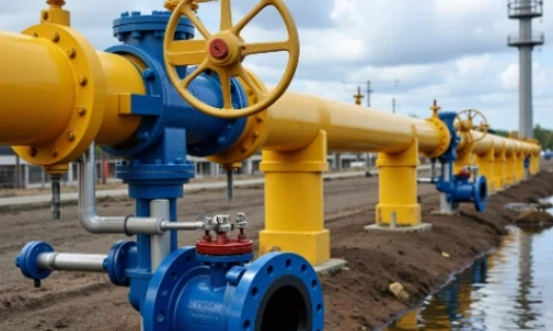
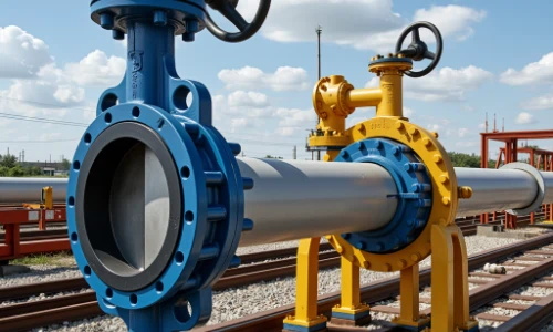
The primary distinction between Wafer, Semi-Lug, and Full-Lug butterfly valves lies in their method of installation and their ability to handle dead-end service, not the total number of bolt holes.
| Attribute | Semi-Lug Type | Full-Lug (Lug) Type |
|---|---|---|
| Image | 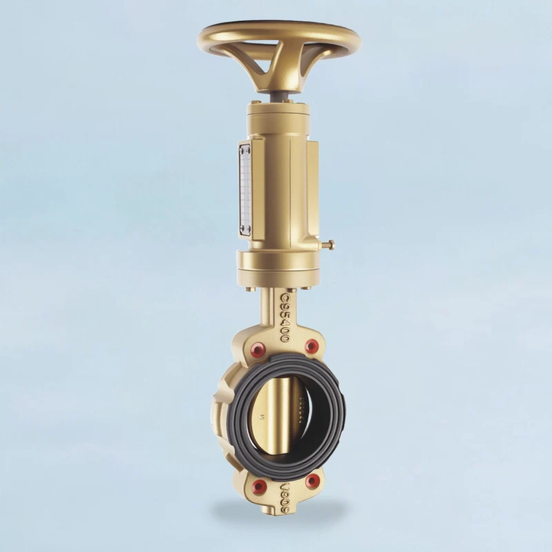 |
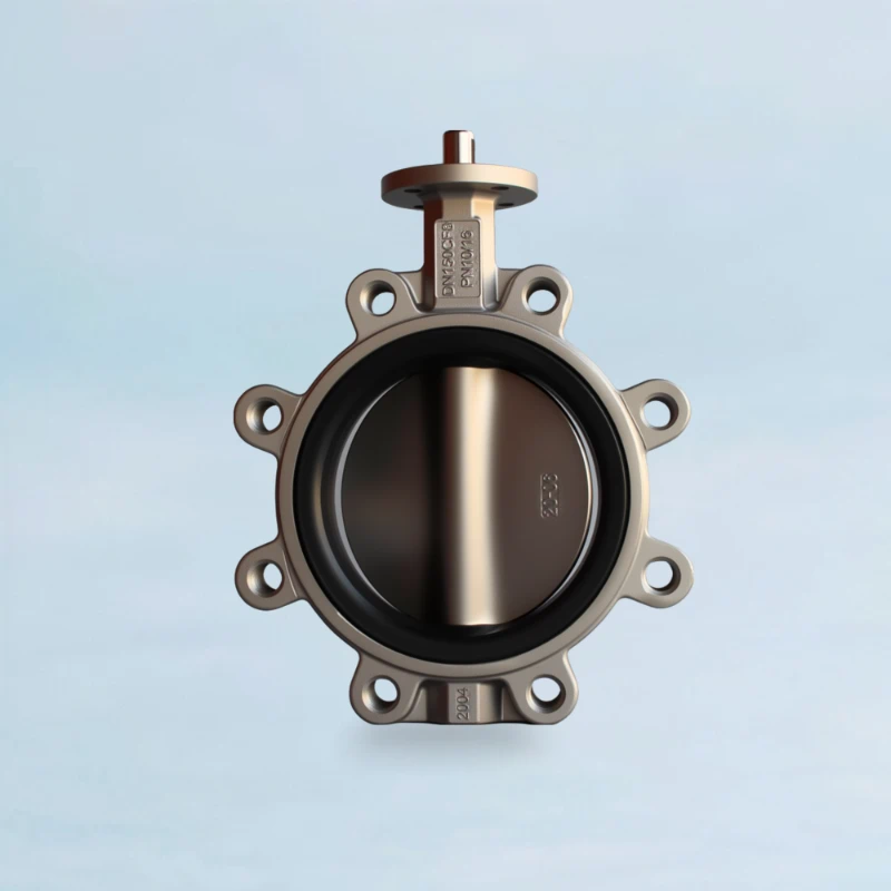 |
| Body Holes | A combination of some threaded holes (for alignment) and some smooth through-holes. | All bolt holes corresponding to the flange standard are fully threaded (tapped). |
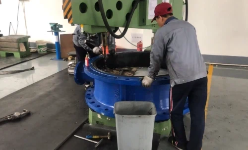
| Installation Method | The valve is initially positioned and aligned using short bolts in the threaded top and bottom lug holes. Final clamping force is then applied by installing long through-bolts in the remaining smooth holes. | Independently bolted to each pipe flange using two separate sets of shorter cap screws. |
| Primary Function | Assisted alignment during installation. Final security relies on through-bolt clamping force. | Provides a structural connection point capable of bearing bolt load independently on each side. |
| Dead-End Service Capability | ❌ NO | ✅ YES |
| Rationale for Dead-End Service | The body is not designed to bear the full bolt load on only the few threaded alignment holes. Removal of one flange will cause failure. | The valve can be bolted securely to one flange, allowing the downstream pipe to be removed for maintenance while the valve maintains a seal. |
| Key Advantage | Easier installation for heavy/large valves compared to wafer type. | System versatility; allows for downstream maintenance without draining the entire line. |
| Relative Cost | Moderate | High |
2. Origin of Bolt Hole Quantity (4, 8, 16 Holes Explained)
A frequent misconception is that the valve's type, such as 'Semi-Lug', determines its number of bolt holes—often incorrectly associating it with having four holes. To be clear: the quantity of bolt holes (whether 4, 8, or 16) is not defined by the valve's body style. Instead, it is strictly governed by the applicable flange standard, which specifies the bolt pattern based on pipe size (NPS/DN) and pressure class.
The Governing Principle
The number of bolt holes, their diameter, and their spacing are dictated by the Nominal Pipe Size (NPS/DN) and the Pressure Class (e.g., ASME Class 150, PN16). Larger pipes and higher pressures require more bolts to safely distribute the force and maintain a seal.
The table below shows an example using the ASME B16.5 Class 150 standard. Any valve type matching this standard will have the same number of hole positions.
| Nominal Pipe Size (NPS) | Approx. DN (mm) | Required Number of Bolt Holes per Flange |
|---|---|---|
| 2" | 50 | 4 |
| 3" | 80 | 4 |
| 4" | 100 | 8 |
| 6" | 150 | 8 |
| 8" | 200 | 8 |
| 10" | 250 | 12 |
| 12" | 300 | 12 |
| 16" | 400 | 16 |
| 20" | 500 | 20 |
| 24" | 600 | 20 |
A Critical Distinction: "Full-Lug" in Appearance vs. Function
After reviewing the bolt charts, a sharp-eyed engineer might notice a discrepancy: the charts demand a high number of bolts for large valves (e.g., 20 for an NPS 24 valve), yet many large-diameter "full-lug" valves in the market have far fewer lugs (e.g., 16).
This observation is correct, and it highlights a critical difference between market terminology and strict engineering standards. The term "Full-Lug" is used in two distinct ways, especially as valve sizes increase.
| Aspect | "True" Full-Lug (Functional Definition) | "Market" Full-Lug (Appearance-Based) |
|---|---|---|
| Primary Definition | A valve that meets the strict functional requirements for dead-end service, as defined by standards like API 609. | A valve that has a full circle of lugs for its physical appearance, distinguishing it from a wafer-style body. |
| Lug / Ear Count | The number of threaded lugs must match the number of holes on the corresponding standard flange (e.g., ASME B16.5, EN 1092-1). | The number of lugs is an optimized design choice by the manufacturer, and is often less than the flange bolt hole count. |
| Primary Lug Function | To be fully load-bearing, allowing one flange to be removed while the valve maintains a seal against full system pressure. | Primarily for alignment and centering during installation. They may also help retain the valve's weight but are not designed for full-pressure dead-end service. |
| Typical Sizing | Common and practical in smaller diameters (e.g., up to NPS 12 / DN 300). Becomes excessively heavy and costly in larger sizes. | The standard design for most large-diameter valves (e.g., above NPS 12 / DN 300) where dead-end service is not required. |
- The Golden Rule for Specification:
When specifying a large-diameter valve, always clarify the intended function. If you require true dead-end service capability, you must explicitly state that the valve needs to be a "True Lug-Type compliant with API 609." Otherwise, you will likely receive a "Market Full-Lug" valve designed for alignment.
4. Visual Guide to Bolt Tightening Sequence
Proper bolt tightening is critical for achieving a leak-free seal and preventing damage to the valve or flanges. The universal best practice is the star pattern (or criss-cross pattern), which ensures gasket load is applied evenly.
4-Bolt Pattern (1-2-3-4)
8-Bolt Pattern (1-2-3-4-5-6-7-8)
The Multi-Pass Process:
- Step 1: Hand Tighten. Snug all bolts by hand in the star sequence to bring flanges into uniform contact with the valve.
- Step 2: First Pass (20-30% Torque). Using a calibrated torque wrench, tighten each bolt in the star sequence to 20-30% of the final required torque.
- Step 3: Second Pass (50-70% Torque). Repeat the star sequence, bringing each bolt to 50-70% of the final torque.
- Step 4: Final Pass (100% Torque). Repeat the star sequence a third time to bring all bolts to their final torque value.
- Step 5: Rotational Pass (Final Check). Perform one final pass, tightening the bolts sequentially (e.g., clockwise) to the final torque to ensure no bolt has relaxed.
Critical Installation Notes
Please note that regardless of the specific diagram, the objective is always the same: to ensure the gasket is uniformly compressed between the valve and the pipe flanges.
An incorrect sequence, such as tightening bolts in a circular (e.g., clockwise 1-2-3-4...) pattern, will lead to critical failures:
Localized Over-compression: One side of the flange is tightened first, which can crush or damage the gasket in that area.
Uneven Sealing Stress: As one side is tightened, the flange tilts slightly, preventing the opposite side from achieving adequate pressure and creating a potential leak path.
Flange Distortion: On large or high-pressure flanges, uneven force can cause permanent deformation (warping) of the flange itself.
This is analogous to tightening the lug nuts on a car wheel, where a criss-cross pattern is mandatory for the exact same reasons. The key is to always tighten bolts in an opposing, alternating sequence to guarantee even pressure distribution.
5. Authoritative References & Further Reading
- API 609 - Butterfly Valves: Double Flanged, Lug- and Wafer-Type
The definitive industry standard specifying design, including the mandatory capability of lug-type valves to handle dead-end service.
View Standard at IHS Markit - ASME B16.5 - Pipe Flanges and Flanged Fittings
This standard governs flange dimensions, including the number and pattern of bolt holes for different sizes and pressure classes.
View Standard at ASME.org
6. Full Lug Butterfly Valve Bolt Charts
Data below represents the required Cap Screws for Full-Lug style valves (Functional Definition). The quantity is double the flange bolt hole count, as each flange is bolted to the valve body independently.
Lug Style: ASME / ANSI Flanges
Critical Note on Bolt Quantity
A Lug valve uses two sets of cap screws. For example, a 6" Class 150 Lug valve requires 16 cap screws (8 for the upstream flange, 8 for the downstream flange).
| NPS | Class 150 | Class 300 | Class 600 | Class 900 | B16.47 Ser. A | B16.47 Ser. B | ||||||
|---|---|---|---|---|---|---|---|---|---|---|---|---|
| Qty. | Size | Qty. | Size | Qty. | Size | Qty. | Size | Qty. | Size | Qty. | Size | |
| 2 | 8 | 5/8 | 16 | 5/8 | 16 | 5/8 | 16 | 3/4 | - | - | - | - |
| 2.5 | 8 | 5/8 | 16 | 3/4 | 16 | 3/4 | 16 | 7/8 | - | - | - | - |
| 3 | 8 | 5/8 | 16 | 3/4 | 16 | 3/4 | 16 | 7/8 | - | - | - | - |
| 4 | 16 | 5/8 | 16 | 3/4 | 16 | 7/8 | 16 | 1 1/8 | - | - | - | - |
| 5 | 16 | 3/4 | 16 | 3/4 | 16 | 1 | 16 | 1 1/4 | - | - | - | - |
| 6 | 16 | 3/4 | 24 | 3/4 | 24 | 1 1/8 | 24 | 1 1/4 | - | - | - | - |
| 8 | 16 | 3/4 | 24 | 7/8 | 24 | 1 1/4 | 24 | 1 1/2 | - | - | - | - |
| 10 | 24 | 7/8 | 32 | 1 | 32 | 1 3/8 | 32 | 1 5/8 | - | - | - | - |
| 12 | 24 | 7/8 | 32 | 1 1/8 | 40 | 1 3/8 | 40 | 1 3/4 | - | - | - | - |
| 14 | 24 | 1 | 40 | 1 1/8 | 40 | 1 1/2 | 40 | 2 | - | - | - | - |
| 16 | 32 | 1 | 40 | 1 1/4 | 40 | 1 5/8 | 40 | 2 1/4 | - | - | - | - |
| 18 | 32 | 1 1/8 | 48 | 1 1/4 | 40 | 1 3/4 | 40 | 2 1/2 | - | - | - | - |
| 20 | 40 | 1 1/8 | 48 | 1 1/4 | 48 | 1 7/8 | 48 | 2 1/2 | - | - | - | - |
| 24 | 40 | 1 1/4 | 48 | 1 1/2 | 48 | 2 | 48 | 3 | - | - | - | - |
| 26 | - | - | - | - | - | - | - | - | 48 | 1 1/4 | 56 | 1 |
| 28 | - | - | - | - | - | - | - | - | 56 | 1 1/4 | 64 | 1 |
| 30 | - | - | - | - | - | - | - | - | 56 | 1 1/4 | 72 | 1 |
| 32 | - | - | - | - | - | - | - | - | 56 | 1 1/2 | 72 | 1 1/8 |
| 34 | - | - | - | - | - | - | - | - | 64 | 1 1/2 | 80 | 1 1/8 |
| 36 | - | - | - | - | - | - | - | - | 64 | 1 1/2 | 88 | 1 1/8 |
| 38 | - | - | - | - | - | - | - | - | 72 | 1 1/2 | 88 | 1 1/4 |
| 40 | - | - | - | - | - | - | - | - | 72 | 1 1/2 | 96 | 1 1/4 |
| 42 | - | - | - | - | - | - | - | - | 80 | 1 1/2 | 104 | 1 1/4 |
| 44 | - | - | - | - | - | - | - | - | 80 | 1 3/4 | 112 | 1 1/4 |
| 46 | - | - | - | - | - | - | - | - | 88 | 1 3/4 | 120 | 1 1/4 |
| 48 | - | - | - | - | - | - | - | - | 88 | 1 3/4 | 120 | 1 1/2 |
| 50 | - | - | - | - | - | - | - | - | 96 | 1 3/4 | 128 | 1 1/2 |
| 52 | - | - | - | - | - | - | - | - | 104 | 1 3/4 | 136 | 1 1/2 |
| 54 | - | - | - | - | - | - | - | - | 104 | 1 3/4 | 144 | 1 1/2 |
| 56 | - | - | - | - | - | - | - | - | 112 | 1 3/4 | 152 | 1 1/2 |
| 58 | - | - | - | - | - | - | - | - | 112 | 2 | 160 | 1 1/2 |
| 60 | - | - | - | - | - | - | - | - | 120 | 2 | 168 | 1 1/2 |
Lug Style: EN 1092-1 (DIN) Flanges
| DN | PN 6 | PN 10 | PN 16 | PN 25 | PN 40 | |||||
|---|---|---|---|---|---|---|---|---|---|---|
| Qty. | Size | Qty. | Size | Qty. | Size | Qty. | Size | Qty. | Size | |
| 50 | 8 | M16 | 8 | M16 | 8 | M16 | 8 | M16 | 8 | M20 |
| 65 | 8 | M16 | 8 | M16 | 8 | M16 | 8 | M20 | 8 | M20 |
| 80 | 16 | M16 | 16 | M16 | 16 | M16 | 16 | M20 | 16 | M24 |
| 100 | 16 | M16 | 16 | M16 | 16 | M20 | 16 | M24 | 16 | M24 |
| 125 | 16 | M16 | 16 | M16 | 16 | M20 | 16 | M24 | 16 | M27 |
| 150 | 16 | M20 | 16 | M20 | 16 | M20 | 16 | M24 | 16 | M27 |
| 200 | 16 | M20 | 24 | M20 | 24 | M20 | 24 | M27 | 24 | M30 |
| 250 | 24 | M20 | 24 | M24 | 24 | M24 | 24 | M30 | 24 | M33 |
| 300 | 24 | M20 | 24 | M24 | 24 | M24 | 24 | M30 | 24 | M36 |
| 350 | 32 | M20 | 32 | M24 | 32 | M27 | 32 | M33 | 32 | M39 |
| 400 | 32 | M24 | 32 | M27 | 32 | M27 | 32 | M36 | 32 | M42 |
| 450 | 40 | M24 | 40 | M27 | 40 | M30 | 40 | M36 | 40 | M45 |
| 500 | 40 | M24 | 40 | M27 | 40 | M30 | 40 | M39 | 40 | M48 |
| 600 | 40 | M27 | 40 | M30 | 40 | M33 | 40 | M45 | 40 | M52 |
Lug Style: JIS B2220 Flanges
| DN | 5K | 10K | 16K | 20K | ||||
|---|---|---|---|---|---|---|---|---|
| Qty. | Size | Qty. | Size | Qty. | Size | Qty. | Size | |
| 50 | 8 | M12 | 8 | M16 | 8 | M16 | 16 | M16 |
| 65 | 8 | M12 | 8 | M16 | 8 | M16 | 16 | M16 |
| 80 | 8 | M16 | 16 | M16 | 16 | M16 | 16 | M20 |
| 100 | 16 | M16 | 16 | M16 | 16 | M20 | 16 | M20 |
| 125 | 16 | M16 | 16 | M16 | 16 | M20 | 16 | M22 |
| 150 | 16 | M16 | 16 | M20 | 16 | M22 | 24 | M22 |
| 200 | 16 | M20 | 24 | M20 | 24 | M22 | 24 | M24 |
| 250 | 24 | M20 | 24 | M22 | 24 | M24 | 24 | M27 |
| 300 | 24 | M20 | 32 | M22 | 32 | M24 | 32 | M27 |
Lug Style: AS 2129 Flanges
| DN | Table D | Table E | ||
|---|---|---|---|---|
| Qty. | Size | Qty. | Size | |
| 50 | 8 | 5/8 | 8 | 5/8 |
| 65 | 8 | 5/8 | 8 | 3/4 |
| 80 | 8 | 5/8 | 8 | 3/4 |
| 100 | 8 | 3/4 | 16 | 3/4 |
| 125 | 16 | 3/4 | 16 | 3/4 |
| 150 | 16 | 3/4 | 16 | 7/8 |
| 200 | 16 | 7/8 | 16 | 1 |
| 250 | 16 | 1 | 24 | 1 |
| 300 | 24 | 1 | 24 | 1 1/8 |
Lug Style: KS B 1503 Flanges
| DN | 5K | 10K | 20K | |||
|---|---|---|---|---|---|---|
| Qty. | Size | Qty. | Size | Qty. | Size | |
| 50 | 8 | M12 | 8 | M16 | 16 | M16 |
| 65 | 8 | M12 | 8 | M16 | 16 | M16 |
| 80 | 8 | M16 | 16 | M16 | 16 | M20 |
| 100 | 16 | M16 | 16 | M16 | 16 | M20 |
| 125 | 16 | M16 | 16 | M16 | 16 | M22 |
| 150 | 16 | M16 | 16 | M20 | 24 | M22 |
| 200 | 16 | M20 | 24 | M20 | 24 | M24 |
| 250 | 24 | M20 | 24 | M22 | 24 | M27 |
| 300 | 24 | M20 | 32 | M22 | 32 | M27 |
Lug Style: GOST 33259 / 12820 Flanges
| DN | PN 10 | PN 16 | ||
|---|---|---|---|---|
| Qty. | Size | Qty. | Size | |
| 50 | 8 | M16 | 8 | M16 |
| 80 | 16 | M16 | 16 | M16 |
| 100 | 16 | M16 | 16 | M20 |
| 125 | 16 | M16 | 16 | M20 |
| 150 | 16 | M20 | 16 | M20 |
| 200 | 24 | M20 | 24 | M20 |
| 250 | 24 | M24 | 24 | M24 |
| 300 | 24 | M24 | 24 | M24 |
Lug Style: GB/T 9113 / 9119 Flanges
| DN | PN 10 | PN 16 | ||
|---|---|---|---|---|
| Qty. | Size | Qty. | Size | |
| 50 | 8 | M16 | 8 | M16 |
| 65 | 8 | M16 | 8 | M16 |
| 80 | 16 | M16 | 16 | M16 |
| 100 | 16 | M16 | 16 | M20 |
| 125 | 16 | M16 | 16 | M20 |
| 150 | 16 | M20 | 16 | M20 |
| 200 | 24 | M20 | 24 | M20 |
| 250 | 24 | M24 | 24 | M24 |
| 300 | 24 | M24 | 24 | M24 |

Authored by the Engineering Team at Tianjin Jiangrui Steel Casting Co., Ltd.
With decades of expertise in fluid control, our engineers provide practical, in-depth knowledge to help you make the right valve selection. Have a complex application or need a quote? Our team is ready to assist.
GET A TECHNICAL CONSULTATION