
 JRVAL
JRVAL Dec 09 2025
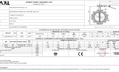
Confusion about P&ID symbols leads to costly mistakes. We use the ISA 5.1 / ISO 10628 Standard to ensure clarity, safety, and precision for our global partners.
Standard P&ID symbols look similar. Use this guide to distinguish a Butterfly Valve from Gate and Globe valves based on Center Detail and Handle Type.
Visual Key: Empty Body + T-Handle.
Visual Key: Solid DOT + T-Handle.
Visual Key: Pivot Dot + Diagonal Lever.
Why do engineers draw a dot or a line in the center? It's not a mistake. It represents the Disc orientation inside the pipe.
Style A: The "Pivot Dot"
What it means: This represents the valve Stem/Shaft seen from the front.
Unlike a Gate Valve (empty center), a Butterfly Valve disc always stays in the center of the flow. This dot confirms: "There is a mechanism here."
Style B: The "Vertical Line"
What it means: This represents the Disc Edge seen from the side.
This is technically more accurate for larger drawings. It shows the disc blocking the path (Closed position) or the profile of the disc (Open position).
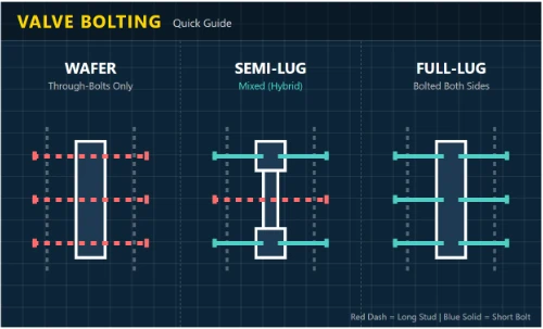
The classic "bowtie" symbol (two triangles). The solid dot in the center distinguishes it from a Gate or Globe valve.
Notice the small circles on the corners? These represent the threaded Lug inserts.
The heavy vertical lines represent the valve's own flanges.
Note: Standard P&ID symbols do not distinguish offset types. Below are the Engineering Schematics used to identify internal design.
Schematic shows the shaft is offset from the seat center.
Schematic highlights the angled cone seat (Red Line).
Analysis: Double vs. Triple Offset
P&ID symbols simplify the geometry, but the internal physics dictate the application. Understand the critical distinction between "Cam-Action Lift" and "Torque Seating".
- Mechanism: Uses the "Cam Effect" to create immediate disc lift-off.
- Friction Mapping: Eliminates sliding friction at 3 & 9 o'clock.
- Benefit: Protects Soft Seats (PTFE) from abrasion, extending cycle life.
- Mechanism: Uses a "Conical Wedge" geometry (Cork-in-bottle).
- Sealing: True Torque Seating rather than position seating.
- Benefit: Enables Zero-Leakage with Metal-to-Metal components.
*Includes detailed diagrams of Offset 1 (Axial), Offset 2 (Radial), and Offset 3 (Conical Profile).
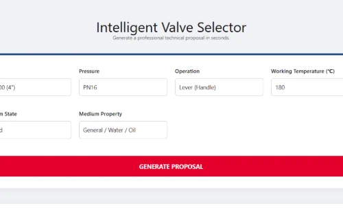
Lever Handle
Used for small sizes (DN50-DN200). Slanted Lever indicates quarter-turn motion.
Worm Gear
Indicates a reduction gearbox is attached. Essential for larger valves where direct manual operation is not feasible due to high torque.
Pneumatic
It visually represents the flexible rubber diaphragm inside the housing that expands with air pressure. If you see a square, it usually means a piston, but the dome is the most common generic symbol.
Electric (Motor)
Requires power supply (24VDC, 110V, 380V).Do not confuse with Solenoid which merely controls air.
Hydraulic Actuator
For massive valves (e.g., Dam, Waterworks) where air or electric motors lack the torque to turn the stem
Technical Distinction: Industrial Butterfly Valves are Pneumatically Actuated, not Direct-Acting. Therefore, the Solenoid ("S") is shown as an accessory connected to the Actuator, not the valve body.
Pneumatic Actuator Only
The semi-circle (Dome) represents the diaphragm/piston housing. Standard ISA symbol.
Pneumatic + Solenoid
The box pilots the air supply.
Correct representation for Industrial Valves.
Pneumatic + Positioner
For modulating control (4-20mA). Ensures precise flow regulation.
Process safety requires defining the valve's position upon loss of power supply (Air, Electricity, or Hydraulic Fluid). The arrow direction on the stem tells the story.
7.1 Pneumatic Actuators (Air Driven)
Most common for fail-safe applications due to the simplicity of mechanical springs.
Mechanism: Spring-Return (Single Acting). Compressed spring forces valve closed when air is lost.
Application: Flammable fluids, toxic gas lines. (Stop the leak).
Mechanism: Spring-Return. Spring forces valve open when air is lost.
Application: Cooling water systems, Fire fighting lines. (Ensure flow continues).
Mechanism: Double Acting + Air Lock Valve. Traps air in the cylinder to hold position.
Application: Precise process control where sudden movement would ruin the batch.
7.2 Electric Actuators (Motor Driven)
Motors are naturally "Fail Last" due to gears. FC/FO requires extra hardware (Batteries/Springs).
Mechanism: Self-locking gear train. When power cuts, the motor simply stops turning.
Mechanism: Requires Battery Backup (UPS) or Super-Capacitor return.
Mechanism: Spring-Return Electric Actuator (small sizes) or Battery UPS (large sizes).
7.3 Hydraulic Actuators (Fluid Driven)
Used for extremely high torque. Fail-safe is achieved via stored pressure (Accumulators).
Mechanism: Hydraulic Accumulator (Pressure Tank) stores energy to stroke the valve when the pump fails.
Mechanism: Pilot operated check valves block the hydraulic lines, hydraulically locking the piston in place.
From Symbol to Reality: Configure Your Actuation System
Understanding the P&ID symbol is just the first step. JRVAL delivers fully assembled and tested pneumatic packages tailored to your specific process requirements.
Choose between cost-effective Double-Acting for general automation or Spring-Return (Fail-Safe) units for Emergency Shutdown (ESD) scenarios.
Integrate Solenoid Valves for piloting, Limit Switch Boxes for position monitoring, and Positioners for precise flow modulation.
*Includes Air Filter Regulators (AFR) & Mounting Kits
P&IDs use "Tag Numbers" to define the function. As a manufacturer, we translate these codes into the physical valve assembly configuration.
"XV" Tag
Process Isolation ValveMeaning: Standard Automated On/Off Valve.
"UZV" / "SDV" Tag
Emergency Shutdown Valve High SpecMeaning: Part of a Safety Instrumented System (SIS).
Requires fast closing time (< 1 sec).
Limit Switch Feedback Signals
When you see bubbles labeled ZSO or ZSC connected to the valve, it means the DCS needs to "see" the valve position.
Sends a signal when the valve is fully OPEN.
Sends a signal when the valve is fully CLOSED.
If your P&ID has these bubbles, you need to order:
Compatible with mechanical (SPDT) or proximity sensors.
The "Box on Top"
You often see a square "S" directly on the valve stem.
Why it's misleading:This represents a Direct-Acting Solenoid Valve (like in a coffee machine). It implies a magnet physically lifts the valve disc.
Physics Reality: A solenoid coil is too weak to turn a heavy industrial butterfly valve.
Solenoid Pilot Configuration
The Solenoid is drawn as an accessory to the Pneumatic Actuator (the dome).
The Engineering Truth:The Solenoid ("S") only controls the air. The Air Actuator (Dome) turns the valve. This symbol tells the engineer: "You need compressed air supply here."
The "Generic T-Handle"
A box with a T-shape on top.
Why it confuses people:In P&ID standards, a "T" usually represents a Handwheel (Multi-turn), like on a garden faucet or Gate Valve. It implies you have to turn it many times to close it.
The Lever / Gear
A simple Diagonal Line (Lever).
The Engineering Truth:Butterfly valves are Quarter-Turn (90°). The diagonal lever symbol visually shows this quick-action movement. For larger valves, we use the specific Gear symbol.
Need Help with Valve Selection?
We provide engineered solutions tailored to your specific process area.