

 JRVAL
JRVAL Aug 01 2025
Archive Index
Cap Screw Fundamentals for Lug Valves
The Role of Lug Style Valves
Lug style butterfly valves feature threaded inserts (lugs) around the body that align perfectly with the bolt holes of the pipeline flange. Unlike Wafer valves, which are "sandwiched" using long stud bolts, Lug valves are secured using separate Cap Screws (Hex Bolts) driven into the valve body from each side independently. This robust design allows Lug valves to be used for Dead-End Service—crucial for system maintenance, equipment isolation, and safety.
The Science of Length & Thread Engagement
Correct Cap Screw length is a non-negotiable parameter. It must be long enough to achieve full, specified thread engagement within the lug for maximum holding power, yet short enough to avoid "bottoming out" (hitting the end of the threaded hole) before the clamping force is achieved. Insufficient engagement can lead to stripped threads under workload. Bottoming out prevents a proper seal and can permanently damage the valve body.
Correct Cap Screw Installation
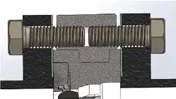
[Image Source: https://manuals.plus/milwaukee-valve/hp1lss4212-high-performance-butterfly-valve-manual]
Measuring Screw Length
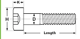
[Image Source: https://monsterbolts.com/products/socket-low-hd-a2-m8]
How to Use This Archive
The master chart below is the most comprehensive single-source reference available. To use it correctly, observe the following principles:
Data Derivation
The Cap Screw length is not arbitrary; it is directly calculated based on the Mating Flange Thickness defined by the applicable standard (e.g., ASME B16.5, EN 1092-1). The lengths provided in this archive are calculated to ensure proper thread engagement without bottoming out. A hyphen (-) or "N/A" indicates that the standard typically does not cover that size/class combination or the data is not applicable.
Quantity (Qty)
The quantities shown represent the number of screws required for ONE flange (one side). For a standard installation between two flanges, you must order double the quantity shown.
The Ultimate Cap Screw Data Chart
Horizontally scrollable master chart covering all major standards. All lengths are in millimeters (mm). Verify all data with the specific valve manufacturer's certified drawings before final design or procurement.
| Valve Size (NPS / DN) |
Pressure Class | Qty (Per Side) |
Thread Size (Inch / Metric) |
American Standards (ASME B16.5/B16.47) | European Standards (EN/BS) | Regional Standards | |||||
|---|---|---|---|---|---|---|---|---|---|---|---|
| B16.5 Length (mm) | B16.47 A (mm) | B16.47 B (mm) | EN 1092-1 (mm) | BS 4504 (mm) | AS 2129 (mm) | GOST (mm) | HG/T (mm) | ||||
| Low Pressure Group: Class 150 (ASME) / PN 10-16 (ISO) | |||||||||||
| 2" / DN50 | CL150 / PN16 | 4 | 5/8" / M16 | 45 | N/A | N/A | 45 | 45 | 45 | 50 | 45 |
| 3" / DN80 | CL150 / PN16 | 4 | 5/8" / M16 | 50 | N/A | N/A | 50 | 50 | 50 | 55 | 50 |
| 4" / DN100 | CL150 / PN16 | 8 | 5/8" / M16 | 50 | N/A | N/A | 55 | 55 | 55 | 55 | 55 |
| 6" / DN150 | CL150 / PN16 | 8 | 3/4" / M20 | 57 | N/A | N/A | 60 | 60 | 60 | 65 | 60 |
| 8" / DN200 | CL150 / PN16 | 8 | 3/4" / M20 | 65 | N/A | N/A | 65 | 65 | 65 | 70 | 65 |
| 12" / DN300 | CL150 / PN16 | 12 | 7/8" / M24 | 76 | N/A | N/A | 80 | 80 | 80 | 90 | 80 |
| 16" / DN400 | CL150 / PN16 | 16 | 1" / M27 | 83 | N/A | N/A | 90 | 90 | - | 100 | 90 |
| 24" / DN600 | CL150 / PN16 | 20 | 1 1/4" / M33 | 108 | N/A | N/A | 110 | 110 | - | 120 | 110 |
| 36" / DN900 | CL150 / PN16 | 32 | 1 1/2" / M39 | N/A | 140 | 130 | 130 | 130 | - | 140 | 130 |
| Medium Pressure Group: Class 300 (ASME) / PN 25-40 (ISO) | |||||||||||
| 2" / DN50 | CL300 / PN40 | 8 | 5/8" / M16 | 50 | N/A | N/A | 45 | 45 | - | 50 | 45 |
| 3" / DN80 | CL300 / PN40 | 8 | 3/4" / M16 | 65 | N/A | N/A | 50 | 50 | - | 55 | 50 |
| 6" / DN150 | CL300 / PN40 | 12 | 3/4" / M20 | 70 | N/A | N/A | 65 | 65 | - | 70 | 65 |
| 8" / DN200 | CL300 / PN40 | 12 | 7/8" / M20 | 83 | N/A | N/A | 70 | 70 | - | 80 | 70 |
| 12" / DN300 | CL300 / PN40 | 16 | 1 1/8" / M27 | 102 | N/A | N/A | 90 | 90 | - | 100 | 90 |
|
ASME Lug Valve Calculation Logic:
Length = Flange Thickness + Gasket (3mm/0.125") + Washer (3mm/0.125") + 1.0x Diameter (Engagement) *Rounded up to nearest 0.25" standard increment. Note on Metric/ISO Standards: EN/BS/GOST lengths are nominal recommendations for PN16/PN40 flanges. Lug body drilling depths vary significantly by manufacturer. |
|||||||||||
Deciphering ASTM Fastener Material Grades
Specifying the correct material grade is just as critical as getting the dimensions right. The material grade defines mechanical strength, temperature limits, and corrosion resistance.
| Grade | Material Specification | Primary Use & Characteristics |
|---|---|---|
| ASTM A193 B7 | Quenched & Tempered Cr-Mo Alloy Steel | The industry workhorse for high-pressure, high-temperature service with carbon and alloy steel flanges. High tensile strength. |
| ASTM A193 B7M | Quenched & Tempered Cr-Mo (100% Hardness Tested) | Engineered for Sour Service (H₂S environments). Hardness controlled to prevent Sulfide Stress Cracking (SSC). |
| ASTM A193 B8 | AISI 304 Stainless Steel (Carbide Solution Treated) | Standard choice for pairing with 304/304L stainless flanges for general corrosion resistance in low-to-medium temperatures. |
| ASTM A193 B8M | AISI 316 Stainless Steel (Carbide Solution Treated) | Superior corrosion resistance compared to B8, specifically against chlorides. Essential for marine, chemical, and pharma applications using 316/316L flanges. |
| ASTM A320 L7 | Quenched & Tempered Alloy Steel (Similar to B7) | Designed for Low-Temperature Service, impact tested down to -101°C (-150°F). Used with LCC/LF2 flanges for cryogenic applications. |
Installation and Torque Protocols
Even perfectly specified screws will fail if installed incorrectly. Proper torque application and tightening sequences are indispensable engineering practices for seal integrity.
The Three Pillars of Proper Fastening
- Calibrated Torque Wrench: Estimation or "feeling it" is unacceptable in the field. A calibrated torque wrench is the only tool that ensures precise, specified clamping force is applied to every fastener.
- Controlled Lubrication: Anti-seize lubricant must be applied to threads and bearing surfaces. This normalizes the coefficient of friction, ensuring that applied torque converts to bolt preload (tension) rather than being lost to friction. Note: Lubricated torque values differ significantly from dry torque values.
- Star Sequence: Always tighten screws in a cross-pattern or "Star" sequence, and do so in multiple stages (e.g., 30%, 60%, 100% of final torque). This protocol ensures the flange compresses the valve face evenly, preventing gasket crushing and uneven stress distribution.
Example: 8-Bolt Star Tightening Pattern
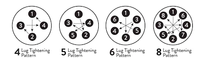
[Image Source: https://www.ladiesoffroadnetwork.com/beginner-lug-nut-torque-and-proper-tightening/]
This principle applies regardless of the bolt count, ensuring uniform compression across the sealing face.
Final Engineering Disclaimer
Important Archive Note: This document is a compilation of publicly available data derived from published international standards. It is an unparalleled resource for preliminary design, planning, and specification.
However, the final authority for any specific application is, and must always be, the technical documentation (Certified Drawings, IOM Manuals) published by the manufacturer of the specific valve model being installed.
Failure to verify with the manufacturer before final procurement constitutes a significant engineering risk.
Need a Complete Solution?
We provide Lug Valves and perfectly matched Cap Screw sets.