
 JRVAL
JRVAL Aug 08 2025
Actuation & Automation Guide: Table of Contents
Part 1: Foundational Concepts
Part 2: Actuator Types
Part 3: Automation & Control
Part 4: Reference Data
1.0 WHAT IS ACTUATION?
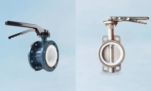
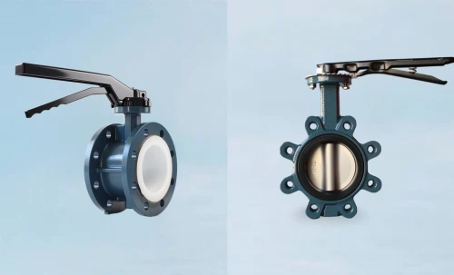
Valve actuation is the mechanism for opening and closing a valve. For butterfly valves, this involves a 90-degree rotation of the disc. Choosing the correct actuator is not just a matter of convenience; it is fundamental to the valve's performance, safety, and operational longevity. An undersized actuator will fail to operate the valve, while an oversized one adds unnecessary cost and weight.
Archivist's Note: The Core Function
At its heart, an actuator converts a source of power—manual, pneumatic, electric, or hydraulic—into the specific mechanical motion (torque and rotation) required by the valve. This guide provides an exhaustive breakdown of each power source and the critical data needed for proper specification and automation.
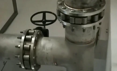
2.0 MANUAL ACTUATION
Manual actuation is the simplest form of valve control, relying on direct human input. It is ideal for applications where actuation is infrequent, power sources are unavailable or unreliable, or when fine-tuned, slow operation is required. The two primary types are lever handles and gearboxes.
2.1 Lever/Handle Actuators
Lever handles provide the most direct and rapid means of operating a butterfly valve. They consist of a handle, a stem adapter, and often a locking device (such as a notch plate) that allows the disc to be secured in various positions. Due to the direct application of force, levers are typically limited to smaller valve sizes, generally up to DN300 (12 inches), beyond which the required operating torque becomes too high for a single operator.
2.2 Gearbox (Worm Gear) Actuators
For larger valves or high-pressure applications where manual operation is still desired, a gearbox is employed. A handwheel is used to turn a worm gear, which in turn rotates a sector gear connected to the valve stem. This mechanism provides significant mechanical advantage, multiplying the operator's input force to generate the high torque needed to actuate the valve. They are a standard solution for ensuring safe and controlled manual operation on high-torque valves.
| Model | Applicable Valve DN (mm) | Output Torque (Nm) | Gear Ratio | Turns to Close | Max Handwheel Ø (mm) | ISO 5211 Flange | Weight (kg) |
|---|---|---|---|---|---|---|---|
| HG-150 | 50 - 150 | 150 | 30:1 | 8 | 200 | F05/F07 | 3.5 |
| HG-300 | 150 - 250 | 300 | 38:1 | 10 | 250 | F07/F10 | 5.0 |
| HG-500 | 250 - 350 | 500 | 45:1 | 12 | 300 | F10 | 8.2 |
| HG-800 | 350 - 450 | 800 | 60:1 | 15 | 400 | F12 | 15.5 |
| HG-1200 | 450 - 600 | 1,200 | 75:1 | 19 | 450 | F14 | 28.0 |
| HG-2500 | 600 - 800 | 2,500 | 110:1 | 28 | 600 | F16 | 55.0 |
| HG-5000 | 800 - 1200 | 5,000 | 180:1 | 45 | 800 | F25 | 110.0 |
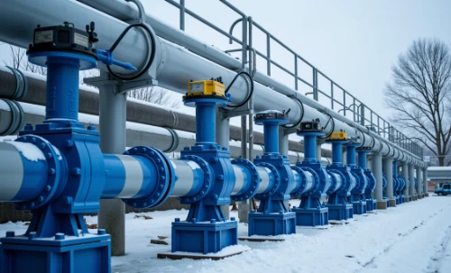
3.0 PNEUMATIC ACTUATION
Pneumatic actuators use compressed air to generate the force required for valve operation. They are renowned for their high reliability, fast cycle speeds, and cost-effectiveness, making them one of the most common choices for automated butterfly valves. Key operating mechanisms include Rack & Pinion and Scotch Yoke.
3.1 Core Operating Mechanisms
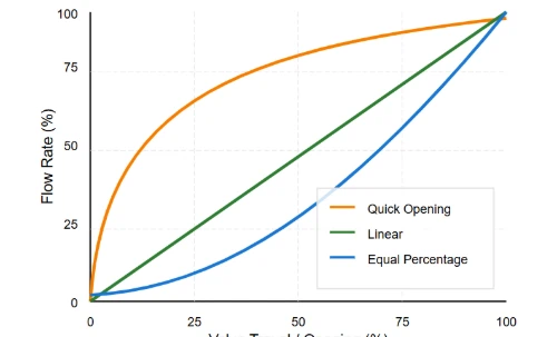
Rack and Pinion: This design features pistons connected to a linear gear (the rack) which engages a circular gear (the pinion) on the output shaft. As compressed air moves the pistons, the rack's linear motion is converted into rotary motion of the pinion, actuating the valve. Its primary advantage is a constant torque output throughout the 90-degree stroke.
Scotch Yoke: This mechanism uses a sliding block on the piston rod that moves within a yoke connected to the output shaft. This design generates a non-linear torque curve, producing very high torque at the beginning and end of the stroke. This makes it ideal for valves that require high "break-away" (opening) and "reseating" (closing) torque.
3.2 Actuator Action Types
Pneumatic actuators are defined by their action upon loss of air pressure, a critical safety consideration.
- Double-Acting (DA): Requires compressed air to both open and close the valve (Air-to-Open, Air-to-Close). Upon loss of air, the valve remains in its last position.
- Spring-Return (SR / Single-Acting): Uses compressed air for one direction of travel and powerful internal springs for the return stroke. This provides a "fail-safe" position.
- Fail-Close (FC) / Normally Closed (NC): Air pressure opens the valve; springs close it on air failure.
- Fail-Open (FO) / Normally Open (NO): Air pressure closes the valve; springs open it on air failure.
3.3 Sizing and Selection
Golden Rules for Pneumatic Actuator Sizing
Proper sizing is non-negotiable for reliable automation. The process involves comparing the actuator's output torque to the valve's required torque, with a safety margin.
- Valve Torque: Obtain the valve's torque requirement from the manufacturer. This includes Break-to-Open (BTO), Running, and End-to-Close (ETC) torques.
- Air Supply: Identify the minimum available plant air pressure at the point of use.
- Safety Factor: Always apply a safety factor to the valve torque. A typical factor is 1.25 to 1.50 (25% to 50%) to account for variables like friction, media changes, and pressure fluctuations.
- Sizing for SR Actuators: This is more complex. You must ensure that both the air stroke torque AND the spring stroke torque exceed the required valve torque (plus safety factor) at every point in the cycle. Pay special attention to the "Spring End Torque," as this is often the lowest value.
Pneumatic Actuator Data: Double-Acting (DA) - Rack & Pinion
| Actuator Model | ISO 5211 Flange | Output Torque (Nm) at Air Supply Pressure | ||||||
|---|---|---|---|---|---|---|---|---|
| 2.5 bar | 3 bar | 4 bar | 5 bar | 6 bar | 7 bar | 8 bar | ||
| PADA-052 | F03/F05 | 15 | 18 | 24 | 30 | 36 | 42 | 48 |
| PADA-063 | F05/F07 | 25 | 30 | 40 | 50 | 60 | 70 | 80 |
| PADA-083 | F07/F10 | 57 | 69 | 92 | 115 | 138 | 161 | 184 |
| PADA-105 | F07/F10 | 106 | 127 | 170 | 212 | 255 | 297 | 340 |
| PADA-125 | F10/F12 | 175 | 210 | 280 | 350 | 420 | 490 | 560 |
| PADA-140 | F12/F14 | 262 | 315 | 420 | 525 | 630 | 735 | 840 |
| PADA-160 | F14/F16 | 405 | 486 | 648 | 810 | 972 | 1134 | 1296 |
| PADA-210 | F16/F25 | 887 | 1065 | 1420 | 1775 | 2130 | 2485 | 2840 |
| PADA-270 | F25 | 1875 | 2250 | 3000 | 3750 | 4500 | 5250 | 6000 |
Pneumatic Actuator Data: Spring-Return (SR) - Rack & Pinion
| Actuator Model | Springs (Qty) | Spring Stroke Torque (Nm) | Air Stroke Torque (Nm) @ 5.5 bar | ||
|---|---|---|---|---|---|
| Start (Air Fail) | End (Air Fail) | Start (Air On) | End (Air On) | ||
| PASR-052 | 12 | 22 | 16 | 21 | 27 |
| PASR-063 | 12 | 37 | 27 | 36 | 46 |
| PASR-083 | 12 | 80 | 57 | 80 | 103 |
| PASR-105 | 12 | 145 | 106 | 140 | 179 |
| PASR-125 | 12 | 240 | 180 | 230 | 290 |
| PASR-140 | 12 | 405 | 295 | 395 | 505 |
| PASR-160 | 12 | 620 | 450 | 600 | 770 |
| PASR-210 | 14 | 1200 | 900 | 1150 | 1450 |
| PASR-270 | 14 | 2750 | 1950 | 2600 | 3400 |
4.0 ELECTRIC ACTUATION
Electric actuators utilize an electric motor and a gear train to produce torque for valve operation. They offer precise control, easy integration with modern control systems (DCS, PLC), and are suitable for a wide range of applications, especially where compressed air is not available. They are available for on/off, modulating, and fail-safe service.
4.1 Core Components
A standard electric actuator is a complex assembly designed for reliability and control:
- Electric Motor: The prime mover, available in various AC and DC voltages.
- Gear Train: Reduces the high speed of the motor into low-speed, high-torque output suitable for valve actuation.
- Logic/Control Board: The 'brain' of the actuator, processing control signals and managing operation.
- Limit & Torque Switches: Mechanical or electronic switches that de-energize the motor at the end of travel (limit switches) or if an obstruction is met (torque switches), protecting both the valve and actuator.
- Manual Override: A handwheel or similar mechanism to operate the valve manually during power failure or commissioning.
4.2 Service Types
- On/Off (Quarter-Turn): The most common type, designed to fully open or fully close the valve.
- Modulating/Throttling: Designed for precise positioning of the valve disc for flow control. These actuators accept analog control signals (e.g., 4-20mA, 0-10V) and have a higher duty cycle rating to withstand frequent movement.
- Fail-Safe: These actuators are designed to move the valve to a pre-determined safe position (open or closed) upon loss of power. This is achieved either through an internal spring-return mechanism or, more commonly, a Battery Backup Unit (BBU).
4.3 Key Technical Parameters
Golden Rules for Electric Actuator Specification
- Duty Cycle: This defines the actuator's permissible operating time. It is critical for modulating applications. Standards like IEC/EN 60034-1 define ratings such as S2 - 15 min (short-time duty) for on/off and S4 - 30% (intermittent duty with 30% on-time, up to 1200 starts/hour) for modulating service. Mis-specifying this can lead to motor overheating and failure.
- Enclosure Protection: The IP (Ingress Protection) or NEMA rating must match the installation environment to protect against dust, water, and corrosion. See table 7.3 for details.
- Voltage and Phase: Must match the available power supply exactly.
- Communication Protocol: For advanced control and diagnostics, specify the required protocol (e.g., Modbus, Profibus, HART).
Electric Actuator Data: On/Off & Modulating Types
| Model | Type | Output Torque (Nm) | Operating Speed (s/90°) | Voltage Options | Power (W) | Duty Cycle | IP/NEMA Rating | ISO 5211 |
|---|---|---|---|---|---|---|---|---|
| E-010 | On/Off | 100 | 15 | 24VDC, 230VAC | 40 | S2 - 15min | IP67 / NEMA 4, 4X | F05/F07 |
| EM-010 | Modulating | 100 | 15 | 24VDC, 230VAC | 40 | S4 - 50% | IP67 / NEMA 4, 4X | F05/F07 |
| E-060 | On/Off | 600 | 30 | 230VAC, 400VAC/3Ph | 120 | S2 - 15min | IP67 / NEMA 4, 4X | F10/F12 |
| EM-060 | Modulating | 600 | 30 | 230VAC, 400VAC/3Ph | 120 | S4 - 50% | IP68 / NEMA 6P | F10/F12 |
| E-120 | On/Off | 1,200 | 45 | 400VAC/3Ph | 370 | S2 - 15min | IP68 / NEMA 6P | F12/F14 |
| EM-120 | Modulating | 1,200 | 45 | 400VAC/3Ph | 370 | S4 - 75% | IP68 / NEMA 6P | F12/F14 |
| E-250 | On/Off | 2,500 | 65 | 400VAC/3Ph | 750 | S2 - 15min | IP68 / NEMA 6P | F14/F16 |
| EM-250 | Modulating | 2,500 | 65 | 400VAC/3Ph | 750 | S4 - 75% | IP68 / NEMA 6P | F14/F16 |
| E-500 | On/Off | 5,000 | 110 | 400VAC/3Ph | 1500 | S2 - 15min | IP68 / NEMA 6P | F16/F25 |
| EM-500 | Modulating | 5,000 | 110 | 400VAC/3Ph | 1500 | S4 - 75% | IP68 / NEMA 6P | F16/F25 |
5.0 HYDRAULIC ACTUATION
Hydraulic actuators use an incompressible fluid, typically oil, to transfer power and generate immense torque. They are the preferred solution for the most demanding applications involving very large diameter butterfly valves, extremely high pressures, or when very high-speed operation is a safety requirement (e.g., Emergency Shutdown Valves - ESD).
Archivist's Note: Systems, Not Just Components
Unlike pneumatic or electric actuators which are often self-contained units, hydraulic actuators are part of a larger system. This system includes the actuator itself (often a heavy-duty Scotch Yoke or Vane type), a Hydraulic Power Unit (HPU) containing a pump, reservoir, and motor, and sophisticated control valve manifolds. Specification is highly specialized and almost always done in direct consultation with the manufacturer to match the exact application requirements.
Hydraulic Actuator Data: Heavy-Duty Scotch Yoke Type (Typical Ranges)
| Model Series | Type | Typical Output Torque Range (kNm) vs. Hydraulic Pressure | ISO 5211 Flange | Max Operating Pressure | ||
|---|---|---|---|---|---|---|
| 70 bar (1000 psi) | 140 bar (2000 psi) | 210 bar (3000 psi) | (bar) | |||
| HSHD-S | Symmetric Scotch Yoke | 10 - 100 kNm | 20 - 200 kNm | 30 - 300 kNm | F25 / F30 / F35 | Up to 350 |
| HSHD-C | Canted Scotch Yoke | 15 - 150 kNm (High Start/End) | 30 - 300 kNm (High Start/End) | 45 - 450 kNm (High Start/End) | F30 / F35 / F40 | Up to 350 |
| HSHD-XL | Symmetric Scotch Yoke | 100 - 500 kNm | 200 - 1000 kNm | 300 - 1500+ kNm | F48 / F60 / Custom | Up to 350 |
|
Note: The data above is representative. Hydraulic actuators are engineered-to-order products. Final torque values, displacement, and dimensions are determined by the manufacturer based on the specific valve, application, and required safety factors. |
||||||
6.0 AUTOMATION ACCESSORIES
A fully automated valve is more than just a valve and an actuator. A suite of accessories is required to control, monitor, and protect the assembly. These components are typically mounted directly to the actuator via standardized interfaces.
6.1 Solenoid Valves
A solenoid valve is an electromechanical valve that directs the flow of compressed air to a pneumatic actuator, telling it to open or close. They are the interface between the electrical control system and the pneumatic actuator.
Key Specs: Mounted via NAMUR (VDI/VDE 3845) interface. A 5/2-way solenoid is used for double-acting actuators (one port for open, one for close). A 3/2-way solenoid is used for spring-return actuators (one port to supply/vent air).
6.2 Limit Switch Boxes
A limit switch box provides remote electrical confirmation of the valve's position (fully open and fully closed). It mounts on top of the actuator and is mechanically linked to the output shaft.
Key Specs: Contains various switch types (e.g., mechanical SPDT, inductive proximity sensors). Enclosures must be specified with the correct IP/NEMA rating and hazardous area certification (e.g., ATEX, IECEx) if required.
6.3 Positioners
Positioners are essential for modulating service. They are advanced controllers that receive a control signal (e.g., 4-20mA) and precisely adjust the air supply to the actuator to move the valve to a specific intermediate position.
Key Specs: Types include pneumatic, electro-pneumatic (I/P), and digital/smart. Smart positioners offer advanced diagnostics and communication via protocols like HART or Fieldbus.
6.4 Air Filter Regulators (AFRs)
An AFR is a critical utility component that ensures the actuator receives a clean, dry, and stable air supply. It filters out contaminants and moisture and regulates the incoming plant air pressure down to the level required by the actuator. This is vital for consistent performance and longevity.
7.0 KEY INDUSTRY STANDARDS
Standardization is the bedrock of interoperability in industrial automation. Adherence to these key standards ensures that actuators, valves, and accessories from different manufacturers can be correctly specified and seamlessly integrated. This section provides exhaustive data tables for the most critical standards in valve actuation.
7.1 ISO 5211:2017 - Part-turn valve actuator attachments
This standard defines the flange dimensions, drive characteristics, and torque ratings for mounting actuators onto quarter-turn valves like butterfly valves. The "F-number" is the universal designator for the mounting interface.
| F-Number | Flange PCD (mm) | No. x Thread | Max Stem Square (mm) | Max Stem Keyed (mm) | Max Flange Torque (Nm) |
|---|---|---|---|---|---|
| F03 | 36 | 4 x M5 | 11 | 11 x 9 | 32 |
| F04 | 42 | 4 x M5 | 14 | 12 x 10 | 63 |
| F05 | 50 | 4 x M6 | 17 | 14 x 11 | 125 |
| F07 | 70 | 4 x M8 | 22 | 19 x 15 | 250 |
| F10 | 102 | 4 x M10 | 32 | 27 x 22 | 500 |
| F12 | 125 | 4 x M12 | 41 | 36 x 28 | 1000 |
| F14 | 140 | 4 x M16 | 54 | 46 x 36 | 2000 |
| F16 | 165 | 4 x M20 | 64 | 55 x 44 | 4000 |
| F25 | 254 | 8 x M20 | 85 | 75 x 60 | 8000 |
| F30 | 300 | 8 x M24 | 108 | 100 x 80 | 16000 |
| F35 | 350 | 12 x M24 | 121 | N/A | 32000 |
| F40 | 400 | 12 x M30 | 141 | N/A | 63000 |
| F48 | 485 | 12 x M36 | 181 | N/A | 125000 |
|
Note: The "Max Flange Torque" values are the maximum permissible torques for the mechanical interface as defined by the ISO 5211 standard. The selected actuator's output torque must not exceed this value for the corresponding F-flange. |
|||||
7.3 IP and NEMA Enclosure Ratings
The IP Code (IEC 60529) and NEMA 250 ratings define the degree of protection an electrical enclosure (like an electric actuator housing) provides against the ingress of foreign objects (dust, dirt) and water.
| NEMA Rating | Protection Against | Typical IP Equivalent |
|---|---|---|
| NEMA 1 | Indoor use, protects against contact with enclosed equipment. | IP20 |
| NEMA 3R | Outdoor use, protects against falling rain, sleet, snow. | IP24 |
| NEMA 4 | Outdoor/Indoor, protects against windblown dust and rain, splashing water, hose-directed water. | IP66 |
| NEMA 4X | Same as NEMA 4, but with added protection against corrosion. Common for chemical plants and coastal areas. | IP66 |
| NEMA 6 | Submersion at a limited depth. | IP67 |
| NEMA 6P | Prolonged submersion at a limited depth, provides extra corrosion protection. The highest standard for valve actuators. | IP68 |
| NEMA 7/9 | For use in specific hazardous locations (Explosion-Proof). Requires ATEX/IECEx certification in other regions. | N/A (Specific Cert.) |
8.0 SUMMARY OF SELECTION CRITERIA
Selecting the optimal actuation and automation package is a systematic process. The following criteria form a decision-making framework to guide you from initial requirements to a fully specified solution.
Power Source Availability
Is compressed air readily available (Pneumatic)? Is reliable electricity the primary utility (Electric)? Or is neither available (Manual)?
Torque & Safety Factor
What is the valve's required torque? Have you applied a sufficient safety factor (min. 25-50%) to ensure reliable operation under all conditions?
Fail-Safe Requirement
In case of power/air failure, must the valve go to a specific safe position (Fail-Open/Fail-Close)? This mandates a Spring-Return pneumatic actuator or an electric actuator with battery backup.
Control Type
Is simple open/close sufficient (On-Off)? Or is precise flow control required (Modulating)? This dictates the choice between basic and advanced actuators (e.g., Electric Modulating or Pneumatic with a Positioner).