
 JRVAL
JRVAL Aug 08 2025
Digital Archive Table of Contents
Part 1: Core Standards
Part 2: Technical Data
Part 3: Ancillary Standards
Part 4: Engineering Guides
Part 1: Core AWWA Standards Overview
The American Water Works Association (AWWA) provides the cornerstone standards for butterfly valves used in municipal water service. This archive primarily focuses on AWWA C504 and C516, which define the design, materials, testing, and performance requirements to ensure reliability and longevity in public water systems.
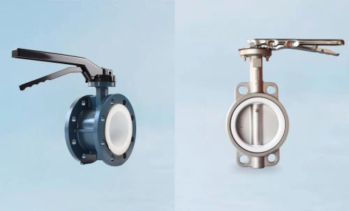
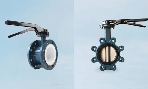
AWWA C504: Rubber-Seated Butterfly Valves
This is the principal standard for rubber-seated butterfly valves, covering nominal pipe sizes from 3 in. (75 mm) through 72 in. (1,800 mm). It establishes requirements for various pressure classes, body types (wafer, lug, flanged), materials, and rigorous testing protocols to guarantee performance under specified service conditions.
AWWA C516: Large-Diameter Rubber-Seated Butterfly Valves
As an extension of C504, this standard specifically addresses the unique engineering challenges of large-diameter butterfly valves, sized 78 in. (2,000 mm) and larger. It details the more stringent requirements for design, fabrication, and testing necessary for these critical, high-consequence components.
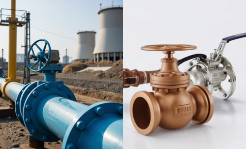
AWWA M44: Distribution Systems—Steel Water Pipe
While not a valve manufacturing standard, the M44 Manual of Water Supply Practices is a critical reference for the proper installation, operation, and maintenance (IOM) of butterfly valves within a water distribution system. Its guidelines are essential for achieving the intended service life and performance of the valve.
Part 2: Comprehensive Technical Data Tables
In compliance with the Principle of Exhaustive Data, the following tables provide a comprehensive collection of specifications derived directly from AWWA standards. All dimensions, materials, and test parameters are presented to facilitate detailed engineering and procurement processes.
2.1 AWWA C504 - Rubber-Seated Butterfly Valves (3" - 72")
2.1.1 Pressure-Temperature Ratings
| Class Designation | Maximum Rated Working Pressure (psig) | Maximum Rated Hydrostatic Test Pressure (psig) | Maximum Service Temperature |
|---|---|---|---|
| Class 25B | 25 | 50 | 125°F (52°C) |
| Class 75A | 75 | 150 | 125°F (52°C) |
| Class 75B | 75 | 150 | 125°F (52°C) |
| Class 150A | 150 | 300 | 125°F (52°C) |
| Class 150B | 150 | 300 | 125°F (52°C) |
| Class 250A | 250 | 500 | 125°F (52°C) |
| Class 250B | 250 | 500 | 125°F (52°C) |
2.1.2 Materials of Construction
| Component | AWWA C504 Specification | Permissible Materials | Applicable ASTM Standard |
|---|---|---|---|
| Body | Cast Iron, Ductile Iron, Carbon Steel, Stainless Steel | Gray Iron, Class B Ductile Iron Cast Steel Fabricated Steel Stainless Steel |
ASTM A126, Class B ASTM A536, Gr. 65-45-12 ASTM A216, Gr. WCB ASTM A36 or A283 ASTM A743/A744, Gr. CF8M |
| Disc | Cast Iron, Ductile Iron, Stainless Steel, Bronze | Ductile Iron Aluminum Bronze Stainless Steel, Type 304 or 316 |
ASTM A536, Gr. 65-45-12 ASTM B148, Alloy C95400 ASTM A743/A744, Gr. CF8/CF8M |
| Shaft (Valve Stem) | Stainless Steel, Monel | Stainless Steel, Type 304, 316, 410, 416, 17-4PH Monel |
ASTM A276 or A582 ASTM B164 |
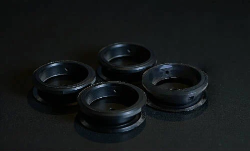
| Seat (Rubber) | Natural or Synthetic Rubber | Buna-N (Nitrile) EPDM Neoprene Viton™ (FKM) |
ASTM D2000 Designation |
| Seat (Metal Backup/Body Seat) | Corrosion-Resistant Material | Stainless Steel, Type 304 or 316 Nickel-Chromium Alloy Bronze |
ASTM A240 or A276 - ASTM B62 |
| Retaining Ring / Segments | Material compatible with body | Ductile Iron Carbon Steel Stainless Steel, Type 304 or 316 |
ASTM A536 ASTM A36 ASTM A240 |
| Bearings / Bushings | Corrosion-Resistant, Self-Lubricating | Sintered Sleeve Bearings (Bronze) Reinforced TFE/Fiberglass Bronze |
ASTM B438, Grade 1, Type II - ASTM B584, Alloy C86300 |
| Packing | Non-asbestos, suitable for water service | V-Type Packing (Buna-N, EPDM) O-Rings (Buna-N, EPDM) |
ASTM D2000 Designation |
| Fasteners (Internal) | Corrosion-Resistant Material | Stainless Steel, Type 304 or 316 Silicon Bronze |
ASTM F593 or A193 Gr. B8/B8M ASTM B98 |
| Fasteners (External) | High-Strength, Corrosion-Resistant Plated | Carbon Steel, Zinc Plated or Galvanized Stainless Steel, Type 304 or 316 |
ASTM A307, Grade B ASTM F593 |
2.1.3 Dimensions and Tolerances (per AWWA C504)
Archivist's Note on Dimensions:
The following tables provide the standard dimensions as specified in AWWA C504. Manufacturers may have slight variations that still fall within acceptable tolerances. Face-to-face dimensions are critical for interchangeability. All dimensions are in inches unless otherwise noted.
| NPS (inch) |
DN (mm) |
Face-to-Face (A) | Min. Body Wall Thickness |
Min. Disc Wall Thickness |
Min. Shaft Diameter | Approx. Wt. Lug (lbs) |
||
|---|---|---|---|---|---|---|---|---|
| Lug Type | Wafer Type | At Disc | Outboard | |||||
| 3 | 80 | 1.88 | 1.88 | 0.31 | 0.25 | 0.75 | 0.62 | 25 |
| 4 | 100 | 2.12 | 2.12 | 0.38 | 0.31 | 0.88 | 0.75 | 35 |
| 5 | 125 | 2.25 | 2.25 | 0.44 | 0.34 | 1.00 | 0.88 | 45 |
| 6 | 150 | 2.25 | 2.25 | 0.44 | 0.38 | 1.12 | 1.00 | 55 |
| 8 | 200 | 2.50 | 2.50 | 0.50 | 0.44 | 1.38 | 1.25 | 90 |
| 10 | 250 | 2.75 | 2.75 | 0.56 | 0.50 | 1.62 | 1.50 | 140 |
| 12 | 300 | 3.00 | 3.00 | 0.62 | 0.56 | 1.88 | 1.75 | 210 |
| 14 | 350 | 3.25 | 3.25 | 0.69 | 0.62 | 2.12 | 2.00 | 300 |
| 16 | 400 | 3.50 | 3.50 | 0.75 | 0.69 | 2.38 | 2.25 | 400 |
| 18 | 450 | 3.75 | 3.75 | 0.81 | 0.75 | 2.62 | 2.50 | 520 |
| 20 | 500 | 4.00 | 4.00 | 0.88 | 0.81 | 2.88 | 2.75 | 680 |
| 24 | 600 | 4.50 | 4.50 | 1.00 | 0.94 | 3.38 | 3.25 | 1050 |
| 30 | 750 | 6.00 | 6.00 | 1.12 | 1.06 | 4.12 | 4.00 | 1850 |
| 36 | 900 | 7.00 | 7.00 | 1.25 | 1.19 | 5.00 | 4.75 | 2900 |
| 42 | 1050 | 8.00 | 8.00 | 1.38 | 1.31 | 5.75 | 5.50 | 4300 |
| 48 | 1200 | 9.00 | 9.00 | 1.50 | 1.44 | 6.50 | 6.25 | 6100 |
| 54 | 1350 | 10.00 | 10.00 | 1.62 | 1.56 | 7.25 | 7.00 | 8500 |
| 60 | 1500 | 11.00 | 11.00 | 1.75 | 1.69 | 8.00 | 7.75 | 11500 |
| 66 | 1650 | 12.00 | 12.00 | 1.88 | 1.81 | 8.75 | 8.50 | 15000 |
| 72 | 1800 | 13.00 | 13.00 | 2.00 | 1.94 | 9.50 | 9.25 | 19000 |
2.1.4 Flange Connection Data (Mating with ASME B16.1 Class 125)
AWWA C504 butterfly valves are designed to fit between flanges conforming to ASME B16.1 (for cast iron) or ASME B16.5 (for steel). The following table details the common Class 125 flange dimensions for reference.
| NPS (inch) |
DN (mm) |
Flange Outer Dia. (OD) |
Min. Flange Thickness |
Bolt Circle Diameter (BCD) |
No. of Bolts |
Bolt Hole Diameter |
Bolt Size (UNC) |
|---|---|---|---|---|---|---|---|
| 3 | 80 | 7.50 | 0.94 | 6.00 | 4 | 0.75 | 5/8" |
| 4 | 100 | 9.00 | 0.94 | 7.50 | 8 | 0.75 | 5/8" |
| 5 | 125 | 10.00 | 0.94 | 8.50 | 8 | 0.88 | 3/4" |
| 6 | 150 | 11.00 | 1.00 | 9.50 | 8 | 0.88 | 3/4" |
| 8 | 200 | 13.50 | 1.12 | 11.75 | 8 | 0.88 | 3/4" |
| 10 | 250 | 16.00 | 1.19 | 14.25 | 12 | 1.00 | 7/8" |
| 12 | 300 | 19.00 | 1.25 | 17.00 | 12 | 1.00 | 7/8" |
| 14 | 350 | 21.00 | 1.38 | 18.75 | 12 | 1.12 | 1" |
| 16 | 400 | 23.50 | 1.44 | 21.25 | 16 | 1.12 | 1" |
| 18 | 450 | 25.00 | 1.56 | 22.75 | 16 | 1.25 | 1 1/8" |
| 20 | 500 | 27.50 | 1.69 | 25.00 | 20 | 1.25 | 1 1/8" |
| 24 | 600 | 32.00 | 1.88 | 29.50 | 20 | 1.38 | 1 1/4" |
| 30 | 750 | 38.75 | 2.12 | 36.00 | 28 | 1.38 | 1 1/4" |
| 36 | 900 | 46.00 | 2.38 | 42.75 | 32 | 1.62 | 1 1/2" |
| 42 | 1050 | 53.00 | 2.62 | 49.50 | 36 | 1.62 | 1 1/2" |
| 48 | 1200 | 59.50 | 2.75 | 56.00 | 44 | 1.62 | 1 1/2" |
| 54 | 1350 | 66.25 | 3.12 | 62.75 | 44 | 1.88 | 1 3/4" |
| 60 | 1500 | 73.00 | 3.38 | 69.25 | 52 | 1.88 | 1 3/4" |
| 66 | 1650 | 79.75 | 3.62 | 76.00 | 56 | 2.12 | 2" |
| 72 | 1800 | 86.50 | 3.88 | 82.75 | 60 | 2.12 | 2" |
2.1.5 Testing & Inspection Requirements
| Test Type | AWWA C504 Reference | Test Pressure | Minimum Duration | Acceptance Criteria |
|---|---|---|---|---|
| Proof of Design (POD) | Sec. 5.1 | Varies by test component | N/A (Type Test) | Valve design must pass a one-time series of rigorous tests to be certified. |
| Hydrostatic Shell Test | Sec. 5.2.1 | 2 x Rated Working Pressure | Per Standard | No visible leakage or structural damage to the body or end connections. |
| Hydrostatic Seat Test | Sec. 5.2.2 | 1.1 x Rated Working Pressure | 5 min | Leakage shall not exceed the rate specified in Sec. 5.2.2.4 of the standard. |
| Cycle Test | Sec. 5.1.4 | Rated Pressure | 500 cycles (POD) | No damage to seat, shaft, or bearings. Final leakage test must meet criteria. |
| Torque Test | Sec. 5.2.3 | Rated Pressure | During Operation | Actuator must seat and unseat the valve against rated pressure without exceeding 80% of its rated torque. |
2.2 AWWA C516 - Large-Diameter Butterfly Valves (>72")
This standard governs rubber-seated butterfly valves in sizes 78 in. and larger, building upon the foundation of C504 with more stringent requirements for design, fabrication, and testing appropriate for their critical service and massive scale.
2.2.1 Dimensions and Tolerances (with Engineering Extrapolation)
| NPS (inch) |
DN (mm) |
Face-to-Face (A) Short Body |
Min. Body Wall Thickness |
Min. Disc Wall Thickness |
Min. Shaft Dia. At Disc |
Approx. Wt. Flanged (lbs) |
|---|---|---|---|---|---|---|
| 78 | 2000 | 18.00 | 2.12 | 2.06 | 10.50 | 24,000 |
| 84 | 2100 | 20.00 | 2.25 | 2.19 | 11.50 | 29,000 |
| 90 | 2250 | 22.00 | 2.38 | 2.31 | 12.50 | 35,000 |
| 96 | 2400 | 24.00 | 2.50 | 2.44 | 13.50 | 42,000 |
| 108 | 2700 | 26.00 | 2.75 | 2.69 | 15.25 | 58,000 |
| 120 | 3000 | 30.00 | 3.00 | 2.94 | 17.00 | 79,000 |
| 132 | 3300 | 33.00 | 3.25 | 3.19 | 18.75 | 105,000 |
| 144 | 3600 | 36.00 | 3.50 | 3.44 | 20.50 | 138,000 |
| 156 | 4000 | 39.00 1 | 3.75 1 | 3.69 1 | 22.25 1 | ~175,000 1 |
| 168 | 4200 | 42.00 1 | 4.00 1 | 3.94 1 | 24.00 1 | ~215,000 1 |
Part 3: Referenced & Ancillary Standards Data
A butterfly valve's performance is intrinsically linked to its actuation, coating, and the specific materials used in its construction. This section provides data from key ancillary standards referenced by or used in conjunction with AWWA C504 and C516.
3.1 AWWA C541 & C542 - Actuators
AWWA C541 (Electric) and C542 (Pneumatic/Hydraulic) define the requirements for actuators used in water service. Key parameters are summarized below.
| Parameter | AWWA C541 (Electric) Requirement | AWWA C542 (Pneumatic/Hydraulic) Requirement |
|---|---|---|
| Enclosure Type | Watertight, NEMA 4 minimum. NEMA 6 for submersible. | Watertight, NEMA 4 minimum. |
| Duty Cycle | Typically 15 minutes, non-continuous. | Continuous duty rated. |
| Motor Voltage | 460V/3Ph/60Hz or 230V/3Ph/60Hz as specified. | N/A |
| Control Voltage | 120V/1Ph/60Hz | Solenoid coils as specified (e.g., 120VAC, 24VDC). |
| Manual Override | Mandatory handwheel for manual operation. | Mandatory handwheel or other means for manual operation. |
| Torque/Limit Switches | Independently adjustable open/close torque and limit switches. | Limit switches for position indication required. |
| Operating Pressure | N/A | Designed for specified air/hydraulic supply pressure (e.g., 80-120 psig air). |
3.2 ISO 5211: Actuator Mounting Flange Dimensions
ISO 5211 is the international standard for actuator mounting interfaces. This ensures interchangeability between valves and actuators from different manufacturers.
| Flange Designation | Bolt Circle Dia. (mm) | No. of Bolts | Bolt Size | Max. Stem Dia. Square (mm) | Max. Stem Dia. Keyed (mm) |
|---|---|---|---|---|---|
| F03 | 36 | 4 | M5 | 11 | 14 |
| F04 | 42 | 4 | M5 | 14 | 17 |
| F05 | 50 | 4 | M6 | 17 | 19 |
| F07 | 70 | 4 | M8 | 22 | 22 |
| F10 | 102 | 4 | M10 | 32 | 32 |
| F12 | 125 | 4 | M12 | 41 | 42 |
| F14 | 140 | 4 | M16 | 55 | 55 |
| F16 | 165 | 4 | M20 | 65 | 65 |
| F25 | 254 | 8 | M16 | 85 | 100 |
| F30 | 300 | 8 | M20 | 100 | 125 |
| F35 | 350 | 8 | M24 | 125 | 150 |
| F40 | 400 | 12 | M24 | 150 | 175 |
3.3 Coatings & Linings (per AWWA C550 & C213)
Protective coatings are critical for corrosion prevention. Fusion-Bonded Epoxy (FBE) is a common high-performance coating for waterworks valves.
| Coating System | Applicable Standard | Location | Min. Dry Film Thickness (DFT) | Holiday Test Voltage |
|---|---|---|---|---|
| Fusion-Bonded Epoxy (FBE) | AWWA C213 | Interior & Exterior | 12-16 mils (300-400 microns) | 100 V per mil of thickness |
| Two-Part Liquid Epoxy | AWWA C210 | Interior & Exterior | 16-20 mils (400-500 microns) | 100 V per mil of thickness |
3.4 ASTM Material Cross-Reference
This table provides a quick reference for the common ASTM material grades specified in AWWA C504.
| ASTM Standard | Material Name / Grade | Common Description & Usage |
|---|---|---|
| ASTM A536 Gr. 65-45-12 | Ductile Iron | Primary material for valve bodies and discs due to its high strength and ductility. |
| ASTM A126 Class B | Gray Cast Iron | Commonly used for valve bodies in lower pressure applications. |
| ASTM A276 Type 316 | Stainless Steel | Standard for valve shafts (stems) and metal seats due to excellent corrosion resistance. |
| ASTM A276 Type 304 | Stainless Steel | Alternative for shafts and metal seats in less corrosive environments. |
| ASTM B148 C95400 | Aluminum Bronze | Used for valve discs, offering excellent resistance to corrosion and erosion. |
| ASTM D2000 | Rubber Compounds (e.g., EPDM, Buna-N) | Specifies the physical properties for rubber seats and seals. EPDM is standard for potable water. |
Part 4: Engineering Application Guides
This final section provides practical engineering data and guidelines essential for the correct application, selection, and maintenance of AWWA butterfly valves. These guides bridge the gap between standards and real-world implementation.
4.1 Flow Coefficients (Cv / Kv) - Estimated Values
The flow coefficient (Cv) represents the flow rate in US Gallons per Minute (GPM) that a valve will pass with a 1 psi pressure drop. Kv is the metric equivalent (m³/h per 1 bar drop). These are typical values for a fully open AWWA butterfly valve; consult the manufacturer for certified data.
| NPS (in) | DN (mm) | Typical Cv (GPM @ 1 psi ΔP) | Typical Kv (m³/h @ 1 bar ΔP) |
|---|---|---|---|
| 3 | 80 | 330 | 285 |
| 4 | 100 | 620 | 535 |
| 6 | 150 | 1,500 | 1,295 |
| 8 | 200 | 2,800 | 2,415 |
| 10 | 250 | 4,500 | 3,880 |
| 12 | 300 | 6,800 | 5,865 |
| 14 | 350 | 9,000 | 7,760 |
| 16 | 400 | 12,500 | 10,780 |
| 18 | 450 | 16,000 | 13,795 |
| 20 | 500 | 21,000 | 18,110 |
| 24 | 600 | 32,000 | 27,600 |
| 30 | 750 | 55,000 | 47,430 |
| 36 | 900 | 85,000 | 73,300 |
| 48 | 1200 | 160,000 | 137,980 |
4.2 Torque Calculation: The Golden Rules
Golden Rules for Actuator Sizing
Valve torque is the rotational force required to open or close the valve. It is not a single value but is influenced by pressure, media, and time. Correct actuator sizing is critical for reliable operation.
- Seating/Unseating Torque: This is the highest torque required, needed to "break" the disc from the rubber seat or to compress the seat for a bubble-tight seal. It is heavily dependent on differential pressure.
- Dynamic Torque: The torque required to operate the valve in a flowing medium. For butterfly valves, this torque tends to try and close the valve and peaks between 70-80 degrees open.
- Safety Factor: Always apply a safety factor to the calculated torque to account for variations in friction, seat swell, and long-term service effects. A minimum safety factor of 1.25 (25%) is standard practice.
- Actuator Output vs. Required Torque: The actuator's rated torque output must exceed the valve's maximum required torque (including the safety factor) at the available operating pressure (for pneumatic/hydraulic actuators).
4.3 Installation, Operation & Maintenance (IOM) Summary
Archivist's Note on IOM
This is a summary of best practices. Always refer to the specific manufacturer's IOM manual before handling, installing, or servicing any valve. Failure to do so can result in valve damage, system failure, and personal injury.
- Installation:
- Ensure mating pipeline flanges are clean, aligned, and spread apart sufficiently to allow the valve to be inserted without damaging the seat.
- The valve disc should be slightly open (approx. 10 degrees) during installation to prevent seat damage.
- Tighten flange bolts in a star/criss-cross pattern to ensure even gasket compression. Do not overtighten.
- Operation:
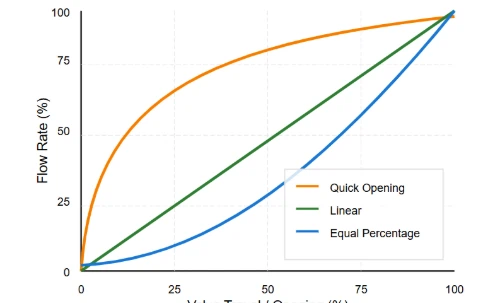
- Do not use butterfly valves for throttling service for extended periods without consulting the manufacturer, as this can cause disc and seat erosion.
- Operate the valve fully open to fully closed periodically (e.g., quarterly) to prevent seizure and verify functionality.
- Maintenance:
- Regularly inspect for external corrosion and leakage from the stem packing or flange joints.
- If the actuator is removed, ensure the valve's position is known and locked out before removing the actuator.
- Stem packing may be adjustable on some models to correct minor leaks. Do not overtighten the packing gland.
AWWA Butterfly Valves
Ready to specify for your project?