
 JRVAL
JRVAL Aug 06 2025
The Ultimate Engineering Guide to Valve Sizing & Flow Coefficients (Cv/Kv)
An archival-grade reference combining fundamental theory, core sizing formulas, and exhaustive flow coefficient data for concentric and high-performance butterfly valves. Your single source of truth for accurate system design.
Introduction to Flow Coefficients: Cv & Kv
The flow coefficient is the single most important parameter for quantifying a control valve's performance. It is a relative measure of a valve's efficiency at allowing fluid to pass through it.
Definition of Cv
Cv is numerically defined as the volume of water at 60°F (in US Gallons per Minute) that will flow through a fully open valve with a pressure drop of 1 psi across the valve.
Definition of Kv
Kv is numerically defined as the volume of water at 20°C (in cubic meters per hour) that will flow through a fully open valve with a pressure drop of 1 bar across the valve.
For international projects, it is essential to convert between Cv and Kv. The conversion factors are derived from the unit conversions of pressure and flow.
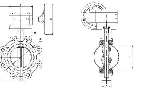
Concentric Butterfly Valve Sizing Chart
Typical flow coefficients for fully open, wafer or lug style resilient-seated concentric butterfly valves. Use for initial planning and quick estimation.
| DN (mm) | Size (inch) | Typical Cv | Typical Kv |
|---|---|---|---|
| DN40 | 1.5" | 75 | 65 |
| DN50 | 2" | 110 | 95 |
| DN65 | 2.5" | 200 | 173 |
| DN80 | 3" | 320 | 277 |
| DN100 | 4" | 550 | 476 |
| DN125 | 5" | 940 | 813 |
| DN150 | 6" | 1,450 | 1,255 |
| DN200 | 8" | 2,800 | 2,422 |
| DN250 | 10" | 4,800 | 4,152 |
| DN300 | 12" | 7,500 | 6,488 |
| DN350 | 14" | 10,500 | 9,083 |
| DN400 | 16" | 14,800 | 12,803 |
| DN450 | 18" | 19,500 | 16,870 |
| DN500 | 20" | 25,000 | 21,625 |
| DN600 | 24" | 40,000 | 34,600 |
| DN700 | 28" | 58,000 | 50,170 |
| DN800 | 32" | 78,000 | 67,470 |
| DN900 | 36" | 105,000 | 90,825 |
| DN1000 | 40" | 140,000 | 121,100 |
| DN1200 | 48" | 210,000 | 181,650 |
| DN1400 | 54" | 290,000 | 250,850 |
| DN1600 | 60" | 380,000 | 328,700 |
| DN1800 | 72" | 520,000 | 449,800 |
| DN2000 | 80" | 680,000 | 588,200 |
| DN2200 | 88" | 850,000 | 735,250 |
| DN2400 | 96" | 1,050,000 | 908,250 |
| DN2600 | 104" | 1,280,000 | 1,107,200 |
| DN2800 | 112" | 1,550,000 | 1,340,750 |
| DN3000 | 120" | 1,850,000 | 1,599,250 |
|
The data for sizes above DN2000 is based on engineering extrapolation from common industry values. These are for preliminary estimation only. Always confirm final Cv/Kv values with manufacturer-certified technical data sheets for the specific valve model selected. |
|||
High-Performance Butterfly Valve (HPBV) Sizing Chart
Typical flow coefficients for double-offset butterfly valves. Note the generally higher efficiency (higher Cv/Kv) compared to concentric valves of the same size, making them ideal for throttling and high-pressure service.
| DN (mm) | Size (inch) | Typical Cv | Typical Kv |
|---|---|---|---|
| DN80 | 3" | 380 | 329 |
| DN100 | 4" | 700 | 606 |
| DN150 | 6" | 1,750 | 1,514 |
| DN200 | 8" | 3,200 | 2,768 |
| DN250 | 10" | 5,500 | 4,758 |
| DN300 | 12" | 8,500 | 7,353 |
| DN350 | 14" | 12,000 | 10,380 |
| DN400 | 16" | 17,000 | 14,705 |
| DN450 | 18" | 22,000 | 19,030 |
| DN500 | 20" | 29,000 | 25,085 |
| DN600 | 24" | 45,000 | 38,925 |
| DN750 | 30" | 75,000 | 64,875 |
| DN900 | 36" | 120,000 | 103,800 |
| DN1050 | 42" | 175,000 | 151,375 |
| DN1200 | 48" | 230,000 | 198,950 |
| DN1400 | 54" | 310,000 | 268,150 |
| DN1500 | 60" | 380,000 | 328,700 |
| DN1600 | 64" | 450,000 | 389,250 |
| DN1800 | 72" | 580,000 | 501,700 |
| DN2000 | 80" | 750,000 | 648,750 |
| DN2400 | 96" | 1,100,000 | 951,500 |
|
The data for sizes above DN1500 is based on engineering extrapolation from common industry values. These are for preliminary estimation only. Always confirm final Cv/Kv values with manufacturer-certified technical data sheets for the specific valve model selected. |
|||
A Note on Triple Offset Valves (TOVs)
You may notice that Cv/Kv values for Triple Offset Butterfly Valves (TOVs) are intentionally omitted from this guide. This is because TOVs are highly engineered, application-specific products, not commodity items.
- Highly Customized: A TOV's flow coefficient is heavily influenced by its specific seal type (e.g., metal-to-metal vs. laminated), pressure class, and intended service. A "typical" value would be dangerously misleading for critical applications.
- Sizing Requires Full Analysis: Selecting a TOV involves a comprehensive engineering analysis including noise prediction, cavitation risk (using its specific FL factor), and torque calculations. Sizing is almost always performed using proprietary manufacturer software by qualified application engineers.
The Golden Rule for TOVs: Always consult directly with the manufacturer for sizing and selection in any critical, high-pressure, or high-temperature service.
Inherent Flow Characteristics
The inherent flow characteristic describes the relationship between the valve's opening (travel) and the flow rate, assuming a constant pressure drop. This property of the valve's geometry is critical for selecting the right valve for control applications.
1. Quick Opening
A large increase in flow occurs with a small amount of initial valve travel. Best for on/off service where immediate maximum flow is needed. Poor for throttling control.
2. Linear
The flow rate is directly proportional to the amount of valve travel. Best for liquid level control and applications where pressure drop across the valve remains constant.
3. Equal Percentage
Each equal increment of travel produces an equal percentage change in the existing flow rate. This is the best choice for most modulating control applications, especially pressure and temperature control.
⚠️ Operational Limits: Recommended Control Range (20% - 70% Opening)
While the flow characteristic curves above are theoretical, optimal throttling performance for Butterfly Valves is strictly limited to a specific range of disc travel.
For process stability and valve longevity, we recommend sizing the valve to operate between 20% and 70% of its opening angle.
At small opening angles, the gap between the disc and the seat is minute, creating extreme high-velocity fluid jets. This "nozzle effect" leads to:
- Erosion / Wire-drawing: Rapid degradation of the sealing surface, leading to leakage when the valve is closed.
- Cavitation (Liquids): Formation and collapse of vapor bubbles that can pit the metal disc.
- Control Instability: A tiny movement of the actuator causes a massive percentage change in flow, causing the system to hunt/oscillate.
As the disc rotates past 70°, the valve body is geometrically almost "full open."
- Diminishing Gain: Moving the valve from 75% to 90% results in a negligible increase in Cv/Flow.
- Loss of Control Sensitivity: The valve loses its ability to fine-tune the process variable. Effectively, the valve acts as a pipe section rather than a control element in this range.
Inherent vs. Installed Characteristics
It is crucial to understand that these "inherent" characteristics are laboratory-defined under a constant ΔP. In a real piping system, the pressure drop changes as the valve opens, distorting the curve. This is the "installed characteristic." An equal percentage valve is popular because its installed characteristic often becomes nearly linear, providing predictable control.
Core Sizing Formulas (ISA/IEC Compliant)
The fundamental formulas to calculate the required flow coefficient (Cv/Kv) for various fluids. Accurate calculation is the mandatory first step to correct valve selection.
Formulas for Liquids (Non-Choked Flow)
- Cv = Required Flow Coefficient
- Q = Flow Rate (US Gallons per Minute, GPM)
- Gf = Specific Gravity of liquid (Water = 1)
- ΔP = Pressure Drop (psi)
Formulas for Gases & Vapors
Gas sizing is more complex due to compressibility. All pressures must be in absolute units (psia/bara).
Non-Choked vs. Choked Flow
For most gases, flow becomes choked (critical) when the pressure drop (ΔP) is roughly half the absolute inlet pressure (P₁). The formulas differ for these two regimes. If ΔP ≥ 0.5 × P₁, use the Choked Flow formula.
Non-Choked (Sub-Critical) Flow
Choked (Critical) Flow
- Q
= Gas Flow Rate (Standard Cubic Feet per Hour, SCFH) - P₁ / P₂ = Inlet / Outlet Pressure (psia)
- Gg = Specific Gravity of gas (Air = 1)
- T = Absolute Temperature (°Rankine = °F + 460)
Formulas for Steam
Choked Flow Condition for Steam
For saturated steam, choked flow occurs when the outlet pressure P₂ is less than or equal to 58% of the absolute inlet pressure P₁. Condition: P₂ ≤ 0.58 × P₁.
Choked Flow (Saturated or Superheated)
- W = Steam Flow Rate (pounds per hour, lbs/hr)
- P₁ = Inlet Pressure (psia)
Advanced Engineering Topics
For critical services, a deeper understanding of fluid dynamics is required to prevent equipment damage and ensure system safety.
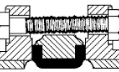
Choked Flow & Pressure Recovery (FL)
The Pressure Recovery Factor (FL) is a dimensionless property of a valve's internal geometry. A lower FL value (e.g., in a high-recovery ball or butterfly valve) means the valve is more susceptible to choking, flashing, and cavitation. This is a critical parameter provided by manufacturers for high-performance valves, used to calculate the true onset of choked flow.
If your actual ΔP exceeds this calculated ΔPmax, the flow is choked, and you must use ΔPmax in the liquid sizing formula.
Valve Noise Prediction (IEC 60534-8)
High-velocity fluid flow generates noise. Levels above 85 dBA are a safety hazard and indicate potentially damaging vibration. Noise prediction is a key part of specification for critical applications, governed by IEC standards.
- Hydrodynamic Noise (Liquids): Caused by cavitation—the violent collapse of vapor bubbles. It sounds like gravel in the pipe and is extremely destructive.
- Aerodynamic Noise (Gases): Generated by turbulent shearing of the fluid. It's the dominant noise source in gas and steam services.
Noise Abatement
The most effective strategy is Source Treatment: selecting a valve with a special low-noise or anti-cavitation trim. This involves multi-stage pressure drop designs that prevent the conditions causing noise and damage.
The Golden Rules of Valve Sizing & Selection
Calculating a Cv is science. Selecting the final valve is engineering art. Ignoring these rules is a common cause of system underperformance, control instability, and premature failure.
Rule #1: Size for Capacity, Select for Control
The calculated Cv only narrows down the potential valve sizes. The final choice must be based on the required flow characteristic and its operating range.
Rule #2: Operate in the "Sweet Spot"
A control valve should ideally operate between 50% and 80% open at the normal flow rate. This provides a buffer for upsets and control authority for turndown.
Rule #3: Check the Velocity
A correct Cv does not protect against excessive fluid velocity, which causes noise and erosion. General limits are <6 m/s (20 ft/s) for clean liquids and < Mach 0.3 for gases.
Rule #4: Identify Choking and Cavitation
Use the FL factor to proactively check for choked flow, flashing, or cavitation. These phenomena guarantee control problems and equipment damage.
Rule #5: Never "Line Size" a Control Valve
A common mistake is selecting a valve with the same size as the pipe. A control valve is a restriction device; it is often one or two sizes smaller than the line.
Rule #6: The Manufacturer is Final Authority
This guide is a comprehensive reference. However, the certified data sheet for the specific valve model you procure is the ultimate source of truth for FL, xT, and Cv.
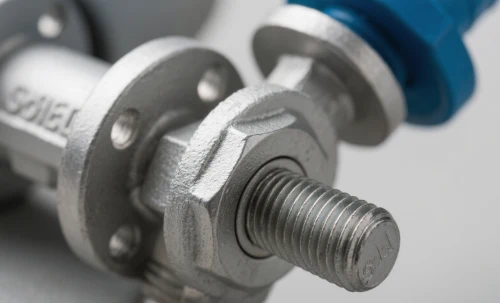
Valves Engineered for Performance
From general utilities to critical high-pressure service, our valves are designed for reliability and control.
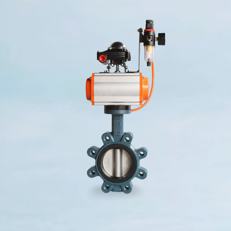
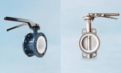
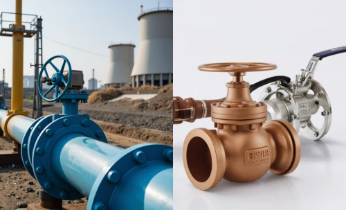
Concentric Resilient-Seated Valve
The workhorse for general purpose applications. Features our innovative bidirectional zero-leakage seat for enhanced reliability at no extra cost.
View Concentric Series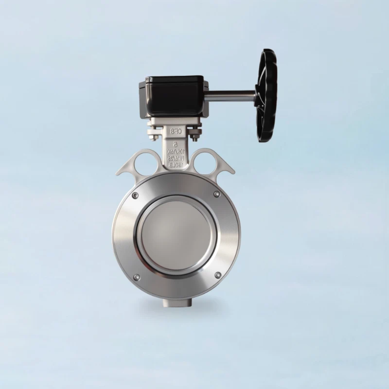
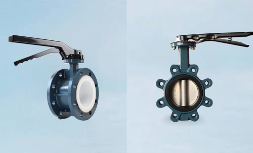
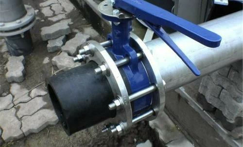
High-Performance Butterfly Valve
Designed for higher pressures, temperatures, and throttling services. The double-offset design reduces seat wear and provides superior control.
Explore HPBV Models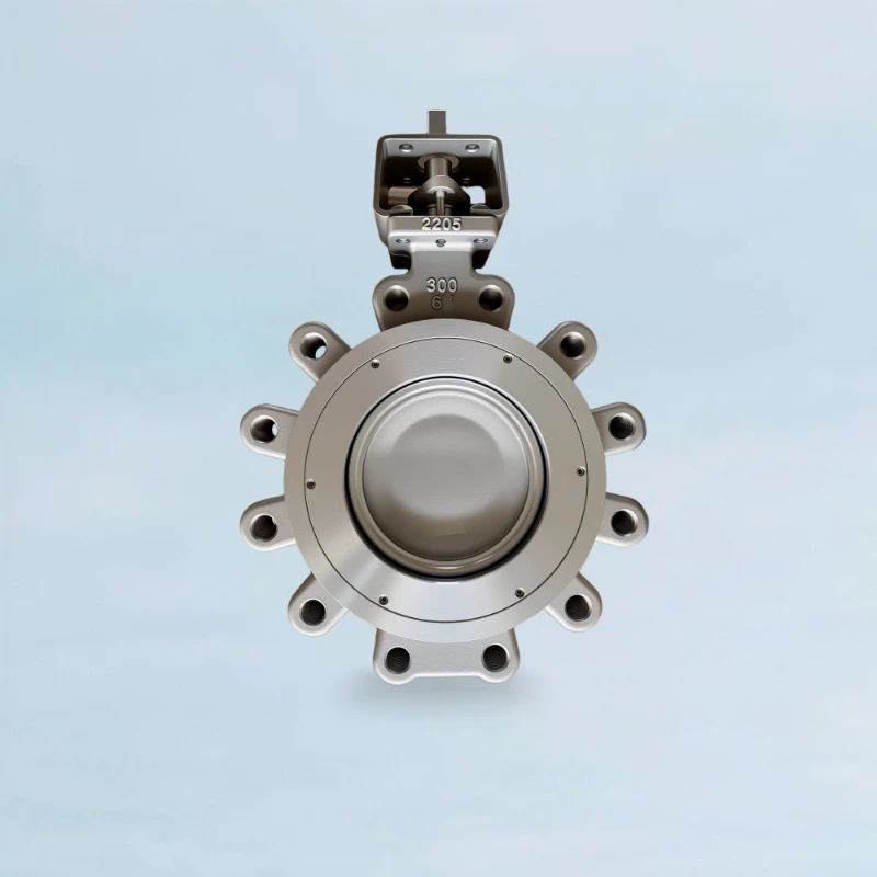
Triple Offset Butterfly Valve
The ultimate solution for critical isolation in severe service conditions, including cryogenic, high-temperature, and hydrocarbon applications.
Discover TOV Solutions