Part 1: Fundamental Principles of Stem Design

1.1 Introduction to the Valve Stem

1.1.1 Role and Criticality of the Stem in a Butterfly Valve Assembly

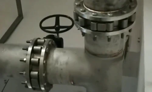
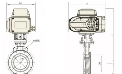
The valve stem, or shaft, is the critical component that connects the external actuator (e.g., a handle, gear operator, or pneumatic/electric actuator) to the internal disc. It is the sole conduit for transmitting the operational torque required to position the disc, thereby controlling the flow of fluid. Its integrity and proper design are paramount to the valve's reliability, safety, and performance. A stem failure results in a complete loss of valve control, potentially leading to catastrophic system failure.

1.1.2 Primary Functions: Torque Transmission, Disc Positioning, and Sealing

The stem serves three primary functions:

  • Torque Transmission: It must withstand and transmit the torque generated by the actuator to overcome hydrodynamic forces, seat/unseat friction, and bearing friction to rotate the disc.
  • Disc Positioning: It must hold the disc securely and accurately in any position from fully open to fully closed, ensuring precise flow modulation and tight shut-off.
  • Sealing: The stem must pass from the "wet" process area inside the valve to the "dry" external environment without allowing process fluid to escape. This is accomplished through a stem sealing system, typically comprising packing rings and glands.

1.1.3 Overview of Stem Types (Rotary Motion)

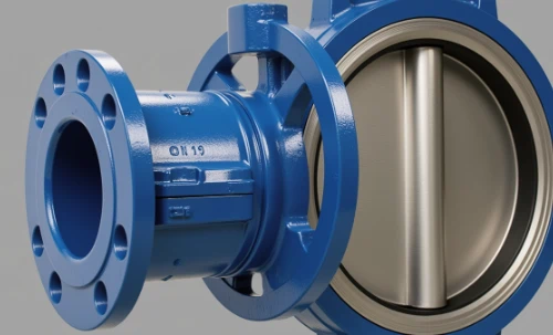
For butterfly valves, which are quarter-turn (90°) rotary devices, stems are designed for rotational motion. The main architectural variations, such as one-piece (through stem) and two-piece (stub stem) designs, are determined by the valve's overall design, pressure class, and intended application. These will be explored in detail in Part 2.

1.2 Core Terminology and Concepts

1.2.1 Torque (Seating, Unseating, Hydrodynamic, Bearing, Packing)

Torque is the rotational force required to operate the valve. The total operational torque is a sum of several components:

  • Seating Torque: The torque required to compress the valve seat and achieve a bubble-tight seal. This is often the highest torque value for resilient-seated valves.
  • Unseating Torque: The torque required to break the disc away from the seat, overcoming static friction and seat adhesion.
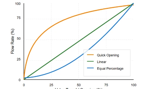
  • Hydrodynamic Torque: The torque generated by the fluid flow acting on the surface of the disc. It is typically highest at partially open positions (e.g., 60-80° open).
  • Bearing Torque: The frictional torque from the stem bearings/bushings that support the stem.
  • Packing Torque: The frictional torque from the stem sealing system (packing).

1.2.2 Stem Blowout and Anti-Blowout Design Features

Stem blowout is a critical failure mode where internal pressure ejects the stem from the valve body. This is a major safety hazard. Modern valve standards (e.g., API 609) mandate anti-blowout designs. This is typically achieved by incorporating a shoulder or collar on the stem that is larger than the stem bore in the valve body, or by using a retaining ring, ensuring the stem is retained by the body even if the actuator is removed under pressure.

1.2.3 Stem Packing, Sealing Mechanisms, and Fugitive Emissions

Stem packing is a system of deformable rings (e.g., PTFE, Graphite) compressed within a packing box to create a seal around the stem. This prevents process fluid from escaping along the stem, a phenomenon known as fugitive emissions. The design of the packing system is critical for environmental compliance and plant safety, especially in toxic or volatile services.

1.2.4 Galling and Anti-Galling Provisions

Galling is a form of severe adhesive wear that can occur between sliding metal surfaces under high contact pressure. It can cause the stem and bearings or stem and disc connection to seize. Prevention involves careful material selection (using materials with different hardnesses and compositions), providing high-quality surface finishes, and using appropriate lubrication or anti-galling coatings/treatments (e.g., nitriding).

1.2.5 Key, Spline, and other Drive Geometries

These are the mechanical interfaces used to transmit torque from the stem to the disc and from the actuator to the stem. Common geometries include square drives, Double 'D' drives, keyed shafts, and splined connections. The choice of geometry depends on the torque requirements, desired precision, and manufacturing cost.

Part 2: Mechanical Design and Engineering

2.1 Stem Architectural Styles

One-Piece Stem (Through Stem)

A single, continuous shaft that runs through the disc and is supported by bearings in both the top and bottom of the valve body.

  • Advantages: Provides maximum support for the disc, resulting in high strength and stability. Ideal for large-diameter valves and high-pressure applications.
  • Disadvantages: Higher manufacturing cost. The stem passes through the waterway, creating a minor flow obstruction.


Two-Piece Stem (Stub Stem)

Consists of two separate shafts (stubs) that connect to the top and bottom of the disc but do not connect to each other through the disc.

  • Advantages: Lower cost. Can offer a higher flow coefficient (Cv) as there is less stem material obstructing the flow path when the disc is parallel to the flow.
  • Disadvantages: The disc is less supported, making this design more suitable for smaller sizes and lower pressure classes.


2.2 Stem-to-Disc Connection Designs

Double 'D' Drive

The stem has two flattened sides, and the disc has a matching Double 'D' shaped hole (broached). Simple and cost-effective for low-to-medium torque.

Square Drive

The stem has a square cross-section that fits into a matching square hole in the disc. A very common, robust, and high-strength connection for high torque transmission.

Splined Connection

The stem and disc have interlocking teeth (splines). This provides excellent, backlash-free torque transmission and precise control. It is a high-performance but more expensive option.

Pinned Connection (Taper or Dowel Pins)

The disc is connected to a round stem using one or more pins drilled through the disc hub and stem. This design is older and less common in modern high-performance valves due to potential wear and fatigue at the pin holes.

2.3 Stem-to-Actuator Interface (Top Works)

2.3.1 ISO 5211 Standard

ISO 5211 is the international standard that governs the mounting dimensions for actuators on quarter-turn valves. It specifies the dimensions of the mounting flange and the drive component (e.g., square or Double 'D' stem drive). Adherence to this standard ensures interchangeability between valves and actuators from different manufacturers, which is a critical requirement for plant operators and engineers.

2.3.2 Common Drive Types (Square, Double 'D', Keyed)

The top of the stem, where the actuator connects, features a specific drive geometry:

  • Square Drive: The most common type for high-torque applications, often oriented at a 45° angle ("on diamond").
  • Double 'D' Drive: Common for smaller valves or where lower torque is expected.
  • Keyed Drive: A round shaft with one or two keyways for transmitting torque via keys. This is more common in gear operators.

2.4 Sizing and Strength Calculations

2.4.1 Minimum Stem Diameter Calculation (Torsional Stress)

The most fundamental calculation ensures the stem can handle the Maximum Allowable Stem Torque (MAST) without yielding. The formula for torsional shear stress in a solid round shaft is used to determine the minimum required stem diameter (D):

T = (τ_max * π * D³) / 16 => D = ³√((16 * T) / (π * τ_max))
D
Minimum required stem diameter.
T
The maximum torque applied to the stem (MAST), which includes a safety factor.
τ_max (Tau_max)
The maximum allowable shear stress of the stem material. This is typically the material's yield strength in shear, divided by a safety factor.
π (Pi)
The mathematical constant ≈ 3.14159.

Part 3: Material Science and Selection

3.1 Factors Influencing Material Selection

Corrosion Resistance

The stem material must be resistant to corrosion from the process fluid. This is often the primary selection criterion. Material selection tables (e.g., NACE MR0175 for sour service) are consulted.

Mechanical Strength (Yield & Tensile)

The material must have sufficient yield strength to handle the operational torque without permanent deformation.

Temperature Range

The material's properties (strength, hardness, corrosion resistance) must be suitable for the entire operating temperature range of the application.

Cost and Availability

The selection is always a balance between engineering requirements and the cost and lead time of the material.

3.2 Common Stem Materials

Stainless Steels
  • 410 SS: A basic, hardenable martensitic stainless steel. Good strength, but limited corrosion resistance. Used in general service (water, air).
  • 17-4PH SS: A precipitation-hardening stainless steel with excellent strength and good corrosion resistance. A very common choice for high-performance stems.
  • 316 SS: An austenitic stainless steel with excellent corrosion resistance but lower strength than 17-4PH. Often used in highly corrosive environments where torque is lower.
High-Nickel Alloys
  • Monel® K500: Excellent resistance to seawater and a wide range of chemicals, combined with very high strength.
  • Inconel® 718: A high-strength, corrosion-resistant nickel-chromium alloy suitable for extreme temperatures and corrosive environments.

Part 4: Manufacturing & Quality Control

4.1 Manufacturing Processes

4.1.1 Stem Machining (Turning, Milling, Grinding)

Stems are typically machined from round bar stock. The process involves:

  • Turning: To create the basic cylindrical diameters and shoulder features.
  • Milling: To create flat features like Double 'D' or square drives.
  • Grinding: To achieve tight dimensional tolerances and a fine surface finish, especially in bearing and sealing areas.

4.2 Quality Assurance and Testing

4.2.1 Dimensional & Geometric Tolerancing (GD&T)

Critical stem dimensions are verified using precision instruments. GD&T controls features like straightness, cylindricity, and runout to ensure proper alignment and function.

4.2.2 Surface Finish Measurement

The roughness of sealing and bearing surfaces is measured to ensure it meets design specifications for low friction and effective sealing.

4.2.3 Material Verification (PMI)

Positive Material Identification (PMI) is a non-destructive testing method used to verify that the chemical composition of the stem material matches the required specification.

4.3 Governing Standards and Specifications

Stem design and manufacturing are governed by several industry standards:

  • API 609: Butterfly Valves: Double Flanged, Lug- and Wafer-Type. (Specifies anti-blowout design).
  • ISO 5211: Part-turn actuator attachments. (Specifies top works mounting).
  • ASME B16.34: Valves—Flanged, Threaded, and Welding End. (Provides pressure-temperature ratings).
  • MSS SP-67: Butterfly Valves.
  • NACE MR0175/ISO 15156: Materials for use in H2S-containing Environments in Oil and Gas Production.

Part 5: Advanced Topics and Failure Analysis

5.1 Stem Sealing Systems

5.1.1 Packing Sets (V-Rings, Braided Packing)

Common packing types include:

  • V-Ring (Chevron) Packing: A set of V-shaped rings (often PTFE) that are pressure-energized, providing a very effective seal.
  • Braided Packing: Braided strands of material (e.g., Graphite, Carbon Fiber) impregnated with lubricants.

5.1.2 Live-Loading

A set of spring washers (e.g., Belleville washers) is installed on the packing gland studs. These springs maintain a constant compressive force on the packing, compensating for wear and thermal expansion, thus reducing the need for frequent adjustment and minimizing fugitive emissions.

5.2 Special Service Considerations

  • Cryogenic Service: Requires an extended bonnet to move the stem packing away from the cold fluid, preventing it from freezing. Materials must be suitable for low-temperature impact toughness.
  • High Temperature Service: Requires materials that retain their strength at elevated temperatures and packing materials like graphite that can withstand the heat.
  • Oxygen Service: Requires special cleaning procedures to remove all hydrocarbons. Materials must be chosen for their compatibility with oxygen to prevent ignition.

5.3 Common Stem Failure Modes

Torsional Shear Failure (Twisting)

Occurs when the applied torque exceeds the material's shear strength. Often seen as a spiral fracture. Caused by oversizing an actuator, "cheater bars" on manual operators, or unexpected process blockages.

Fatigue Failure

Caused by cyclic loading (repeated opening/closing). A crack initiates at a stress concentration point (e.g., keyway, pinhole) and propagates over time until the remaining cross-section can no longer support the load.

Corrosion Failure

Incorrect material selection leads to general corrosion, pitting, or stress corrosion cracking (SCC), severely reducing the stem's effective diameter and load-bearing capacity.

Bending Failure

Caused by excessive side-loading on the stem, often due to actuator misalignment or high hydrodynamic forces on an inadequately supported disc (common in two-piece stem designs).

Part 6: Appendices

Appendix A: Material Properties Table (Typical Values at Ambient Temp)

Material UNS No. Yield Strength (min, ksi) Tensile Strength (min, ksi) Hardness (max)
410 Stainless Steel S41000 85 110 22 HRC
17-4PH Stainless Steel (H1150) S17400 105 135 33 HRC
316 Stainless Steel S31600 30 75 95 HRB
Monel K500 (Aged) N05500 100 140 27-32 HRC
Inconel 718 (Aged) N07718 150 180 36 HRC

Appendix B: ISO 5211 Data Table (Common Flange Types)

Flange Type Mounting Circle (mm) Drive Details
Square (mm) Depth (min)
F03 36 9 11
F04 42 11 14
F05 50 14 17
F07 70 17 22
F10 102 22 27
F12 125 27 32
F14 140 36 42
F16 165 46 55

Appendix C: Torque Calculation Worksheets

Torque Calculation Worksheet (Resilient Seated) 1. Seating Torque (Tseat): Nm (from Mfr. data) 2. Bearing Torque (Tbear): Nm 3. Hydrodynamic Torque (Thyd): Nm (at max ΔP) 4. Packing Torque (Tpack): Nm Total Required Torque (Treq): Nm Note: Treq = Tseat + Tbear + Thyd + Tpack. Apply safety factor as per project spec. Flow Characteristic Curve 0% 100% Open Torque Equal Percentage

Appendix D: Standard Cross-Reference

Feature Primary Standard Alternative/Regional Standard
General Valve Design API 609 MSS SP-67, EN 593
Actuator Mounting ISO 5211 (Widely adopted, no common alternative)
Material Specifications ASTM / ASME EN (e.g., 1.4408), JIS
End-to-End Dimensions API 609 (Cat A/B) ISO 5752, ASME B16.10

Appendix E: Glossary of Terms

MAST (Maximum Allowable Stem Torque)
The maximum torque that can be applied to the stem without causing damage to it or any other valve component. This is a critical safety rating provided by the manufacturer.
Cv (Flow Coefficient)
A value representing the flow capacity of a valve. It is defined as the number of US gallons of water per minute at 60°F that will flow through the valve with a pressure drop of 1 psi.
Quarter-Turn Valve
A valve that operates from fully open to fully closed with a 90-degree rotation of the stem, such as a butterfly valve or a ball valve.
Resilient Seated
A valve design where the seal is achieved by compressing a soft, elastomeric seat (e.g., EPDM, Buna-N) against the disc. This provides bubble-tight shut-off but is limited by temperature and chemical compatibility.
High-Performance Butterfly Valve (HPBV)
A valve design, often with a double-offset disc geometry, capable of handling higher pressures and temperatures than standard resilient-seated valves. They can have soft or metal seats.