
 JRVAL
JRVAL Aug 09 2025
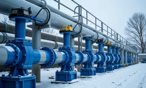
An exhaustive engineering archive dedicated to the design principles, classifications, applications, and technical specifications of concentric and eccentric butterfly valves. This document serves as a high-fidelity resource for engineers, designers, and procurement specialists.
1.0 Foundational Principles & Core Classifications
The primary distinction between butterfly valve types lies in the geometric relationship between the disc, stem, and seat. This geometry dictates the valve's sealing mechanism, performance characteristics, operational lifespan, and suitability for various industrial applications. Understanding these core concepts is essential for proper valve selection.
Concentric (Zero Offset)
Also known as a center-lined or resilient-seated butterfly valve, this is the most basic design. The stem passes through the centerline of the disc, which is also the centerline of the valve body. Sealing is achieved by the disc compressing against a soft, elastomeric or polymer seat.
Sealing Principle: Interference Fit & Compression
Eccentric (Offset)
In an eccentric design, the stem is offset from the centerline of the disc and/or the valve body. This geometry creates a cam-like action, moving the disc out of contact with the seat upon opening. This design can be single, double, or triple offset, with each providing progressively lower friction and better performance in demanding services.
Sealing Principle: Torque-Energized & Positional Sealing
2.0 The Concentric (Zero Offset) Butterfly Valve
Design, Performance, and Applications
The concentric design relies on the flexibility and resilience of its soft seat. As the valve closes, the edge of the disc sinks into the seat, creating a large-area, bubble-tight seal. This constant contact, however, is both its strength and weakness. It ensures excellent sealing in low-pressure applications but also leads to friction and seat wear over time, limiting its use in throttling or high-cycle services. Its simple construction makes it a cost-effective choice for general purpose and utility lines.
Performance Characteristics
Primarily suited for on/off services where tight shut-off is critical.
Typical Application Areas
Ideal for low-pressure, clean fluid applications.
Exhaustive Data: API 609 Cat. A / EN 593 Resilient-Seated Valves
| NPS (inch) | DN (mm) | Face-to-Face (API 609 Cat. A, mm) | Face-to-Face (EN 558 S20, mm) | Pressure Rating (Wafer/Lug) | Common Body Mat. | Common Disc Mat. | Common Seat Mat. | Temp. Range (°C) | Approx. Weight (kg) |
|---|---|---|---|---|---|---|---|---|---|
| 2 | 50 | 43 | 43 | Class 150 / PN16 | Ductile Iron | SS316 | EPDM | -30 to 120 | 4 |
| 3 | 80 | 46 | 46 | Class 150 / PN16 | Ductile Iron | SS316 | EPDM | -30 to 120 | 6 |
| 4 | 100 | 52 | 52 | Class 150 / PN16 | Ductile Iron | SS316 | NBR | -10 to 80 | 9 |
| 6 | 150 | 56 | 56 | Class 150 / PN16 | Ductile Iron | Al-Bronze | NBR | -10 to 80 | 15 |
| 8 | 200 | 60 | 60 | Class 150 / PN16 | Cast Iron | SS316 | Viton (FKM) | -20 to 200 | 25 |
| 10 | 250 | 68 | 68 | Class 150 / PN16 | WCB | SS316 | PTFE | -30 to 200 | 40 |
| 12 | 300 | 78 | 78 | Class 150 / PN16 | WCB | Duplex SS | EPDM | -30 to 120 | 58 |
| 14 | 350 | 78 | 78 | Class 150 / PN10 | Ductile Iron | SS316 | EPDM | -30 to 120 | 85 |
| 16 | 400 | 102 | 102 | Class 150 / PN10 | Ductile Iron | SS316 | EPDM | -30 to 120 | 115 |
| 20 | 500 | 127 | 127 | Class 150 / PN10 | Ductile Iron | SS316 | EPDM | -30 to 120 | 210 |
| 24 | 600 | 154 | 154 | Class 150 / PN10 | Ductile Iron | SS316 | EPDM | -30 to 120 | 320 |
| 36 | 900 | 203 | 203 | PN10 | Ductile Iron | SS316 | EPDM | -30 to 120 | 850 |
| 48 | 1200 | 254 | 254 | PN10 | Ductile Iron | SS316 | EPDM | -30 to 120 | 1700 |
3.0 The Eccentric (Offset) Butterfly Valve
Eccentric butterfly valves were engineered to overcome the limitations of the concentric design. By introducing one or more offsets to the stem's position, the disc is able to lift off the seat in a "cam" or "quarter-turn elliptical" motion. This drastically reduces friction, minimizes wear, and allows for the use of more robust sealing materials, including metal, for high-pressure and high-temperature applications.
Double Offset (High-Performance)
The workhorse of process industries. The stem is offset from both the disc centerline and the valve centerline. This geometry ensures the seal only makes contact during the final few degrees of closing, virtually eliminating friction during the 90° rotation and extending valve life significantly.
Triple Offset (TOV)
The ultimate solution for critical and severe service applications. It adds a third offset: the seat cone axis is angled relative to the valve centerline. This creates a friction-free, torque-seated metal-to-metal seal. The result is a bubble-tight, zero-leakage valve capable of handling extreme pressures, temperatures, and cryogenic conditions.
Single Offset
A less common design where the stem is offset only from the disc's centerline. It was an early attempt to reduce seat wear but has been largely superseded by the superior performance of double and triple offset designs. It is typically found in legacy systems or specialized, niche applications.
Exhaustive Data: API 609 Cat. B (Double Offset / HPBV)
| NPS | DN | Class 150 F-F (mm) | Class 300 F-F (mm) | Class 600 F-F (mm) | Body Material | Disc Material | Seat Material | Pressure Class | Bolt Qty (Cl 300) | Bolt Size (Cl 300) | Approx. Weight (kg, Cl 300) |
|---|---|---|---|---|---|---|---|---|---|---|---|
| 3 | 80 | 114 | 127 | 165 | WCB | SS316 | RPTFE | 150-600 | 8 | 3/4" | 18 |
| 4 | 100 | 108 | 140 | 191 | WCB | SS316 | RPTFE | 150-600 | 8 | 3/4" | 25 |
| 6 | 150 | 127 | 152 | 241 | CF8M | CF8M | TFM 1600 | 150-600 | 12 | 7/8" | 45 |
| 8 | 200 | 140 | 165 | 292 | CF8M | CF8M | RPTFE | 150-600 | 12 | 1" | 75 |
| 10 | 250 | 152 | 178 | 330 | WCB | SS316 | RPTFE | 150-600 | 16 | 1 1/8" | 120 |
| 12 | 300 | 165 | 191 | 356 | WCB | SS316 | RPTFE | 150-600 | 16 | 1 1/4" | 180 |
| 16 | 400 | 191 | 216 | 432 | WCB | SS316 | RPTFE | 150-600 | 20 | 1 3/8" | 350 |
| 20 | 500 | 216 | 241 | 508 | WCB | SS316 | RPTFE | 150-600 | 24 | 1 1/2" | 580 |
| 24 | 600 | 241 | 267 | 559 | WCB | SS316 | RPTFE | 150-600 | 24 | 1 5/8" | 900 |
| 30 | 750 | 267 | 318 | 660 | WCB | SS316 | RPTFE | 150-600 | 28 | 1 3/4" | 1600 |
| 36 | 900 | 318 | 368 | 711 | WCB | SS316 | RPTFE | 150-600 | 32 | 2" | 2500 |
| 42 | 1050 | 356 | 406 | 838 | WCB | SS316 | RPTFE | 150-600 | 36 | 2" | 3800 |
| 48 | 1200 | 394 | 457 | 914 | WCB | SS316 | RPTFE | 150-600 | 44 | 2" | 5200 |
Exhaustive Data: API 609 Cat. B (Triple Offset / TOV)
| NPS | DN | Class 150 F-F (mm) | Class 300 F-F (mm) | Class 600 F-F (mm) | Class 900 F-F (mm) | Body Material | Disc Material | Seal Material | Temp. Range (°C) | Approx. Weight (kg, Cl 600) |
|---|---|---|---|---|---|---|---|---|---|---|
| 3 | 80 | 114 | 127 | 165 | 210 | A216 WCB | A351 CF8M | SS316+Graphite | -196 to 650 | 28 |
| 4 | 100 | 108 | 140 | 191 | 216 | A216 WCB | A351 CF8M | SS316+Graphite | -196 to 650 | 40 |
| 6 | 150 | 127 | 152 | 241 | 292 | A351 CF8M | A351 CF8M | SS316+Graphite | -196 to 650 | 70 |
| 8 | 200 | 140 | 165 | 292 | 330 | A351 CF8M | A351 CF8M | SS316+Graphite | -196 to 650 | 110 |
| 10 | 250 | 152 | 178 | 330 | 368 | A216 WCB | A351 CF8M | SS316+Graphite | -196 to 650 | 190 |
| 12 | 300 | 165 | 191 | 356 | 400 | A216 WCB | A351 CF8M | SS316+Graphite | -196 to 650 | 280 |
| 16 | 400 | 191 | 216 | 432 | 489 | A216 WCB | A351 CF8M | SS316+Graphite | -196 to 650 | 550 |
| 24 | 600 | 241 | 267 | 559 | 610 | A216 WCB | A351 CF8M | SS316+Graphite | -196 to 650 | 1400 |
| 36 | 900 | 318 | 368 | 711 | 775 | A216 WCB | A351 CF8M | SS316+Graphite | -196 to 550 | 3200 |
| 42 | 1050 | 356 | 406 | 838 | 902 | A216 WCB | A351 CF8M | SS316+Graphite | -196 to 550 | 4800 |
| 60 | 1500 | 457 | 559 | 1092 | 1181 | A216 WCB | A351 CF8M | SS316+Graphite | -196 to 550 | 9500 |
| 80 | 2000 | - | - | 1397 | 1505 | Fabricated CS | Fabricated SS | SS316+Graphite | -29 to 450 | 18000 |
|
*Note on DN2000 (80 inch) data: Face-to-face dimensions and weights for valves of this magnitude are not standardized and fall outside the scope of published ASME B16.10 / API 609 tables. The values provided are based on engineering principles and common industry practice for large-diameter fabricated valves. These figures are for reference only and must be confirmed by the manufacturer during the final design and engineering phase. |
||||||||||
4.0 Comparative Analysis & Selection Guide
Choosing the correct butterfly valve requires a systematic evaluation of the application's demands against the capabilities of each design type. This matrix provides a direct comparison across key engineering factors to guide the selection process.
Sealing Performance
Concentric
Bubble-tight bi-directional seal via soft seat compression. Excellent for general service but prone to wear.
Double Offset
Low-friction cam action. Excellent sealing with soft or metal seats. Bi-directional, but may have a preferred flow direction for optimal performance.
Triple Offset
Friction-free, torque-seated metal-to-metal cone sealing. Provides true zero-leakage, bi-directional shut-off, even in severe service.
Pressure & Temperature Range
Concentric
Low pressure (up to PN16/Class 150) and limited temperature (typically -30°C to 200°C) dictated by the elastomer seat.
Double Offset
Medium pressure/temperature. Can handle up to PN100/Class 600 and temperatures from cryogenic to ~450°C, depending on seat/body materials.
Triple Offset
High pressure/temperature. Designed for PN160/Class 900+ and extreme temperatures from cryogenic (-196°C) to over 650°C.
Service Life & Durability
Concentric
Lower lifespan, especially in high-cycle or throttling applications due to constant seat friction and wear.
Double Offset
Significantly longer lifespan due to reduced friction. Seat is more protected and durable.
Triple Offset
Highest durability and longest service life. The friction-free design and robust all-metal construction resist wear and thermal cycling.
Application & Cost
Concentric
Low Cost. Best for utilities, water, HVAC, and general on-off duties where conditions are not demanding.
Double Offset
Medium Cost. The standard for process industries: chemical, oil & gas (non-critical), power generation, pulp & paper.
Triple Offset
High Cost. Reserved for critical services: high-pressure steam, cryogenic LNG, emergency shutdown (ESD), and severe chemical applications.
Need Help Selecting a Valve?
Our engineers are ready to assist with your application.