 JRVAL
JRVAL Jan 31 2026
A deep dive into the precision machining, drilling, and quality control protocols for high-performance valves.
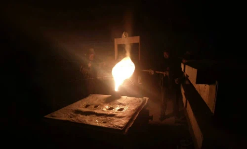
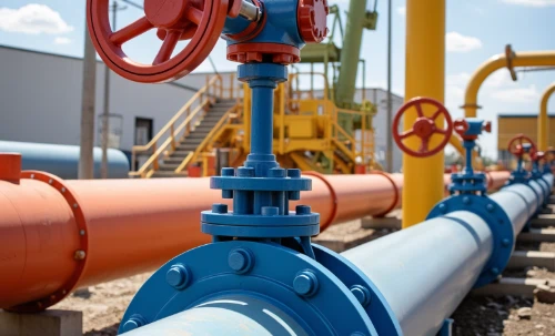
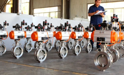
Manufacturing large-diameter valves requires a distinct approach compared to smaller components. At our China Butterfly Valve Factory, the processing of a DN350 (14-inch) Lug Type Butterfly Valve involves strict adherence to dimensional accuracy and surface finish requirements. Below is the detailed step-by-step workflow used to ensure every valve meets international standards.
If you are sourcing high-quality components, you can view our catalog here: Wholesale Lug Butterfly Valve.
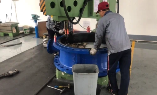
Phase 1: First Operation – Datum & Sealing Surface (Vertical Lathe)
For large-diameter valves (DN350 and above), stability is key. We utilize a Vertical Lathe (VTL) rather than a horizontal one to handle the weight and ensure concentricity.
- Face Turning: We machine the sealing surfaces (flange connection faces) on both sides of the valve body to achieve the required surface roughness (Ra).
- Boring the Inner Hole: This is the critical zone where the valve disc and seat (liner) will sit. The bore must be perfectly circular.
- Deburring: Removal of sharp edges generated during casting and turning to prevent injury and ensure proper coating adhesion later.
Objective: Establish the machining datum and ensure the valve body width (structural length) strictly meets the standard.
Phase 2: Second Operation – Top Flange Processing (Milling)
The top flange connects the actuator (gearbox, pneumatic, or electric actuator). It usually follows the ISO 5211 standard.
- Milling the Plane: We ensure the top flange surface is perfectly parallel to the valve body channel centerline.
- Keyway/Shaft Hole: Machining the central hole to ensure the valve stem passes through smoothly without binding.
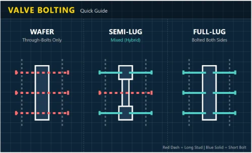
Phase 3: Third Operation – Lug Hole Machining (Drilling & Tapping)
This is the most critical step for Lug valves, as the body is full of threaded holes. Precision is non-negotiable to align with Flange Standards (ASME/JIS/DIN).
1. Marking and Positioning
For non-CNC operations (like radial arm drilling), operators use a specific Drilling Template to overlay on the flange face, using a center punch to mark the "dimples" for positioning.
2. Drilling the Bottom Hole
Drill bits are not chosen at random. Based on the thread standard (Metric or UNC) and material hardness, we select the specific diameter (e.g., Drill Dia = Thread Dia - Pitch).
3. Tapping (Threading)
Creating the internal threads requires high precision. The center-to-center distance error is controlled within 0.1mm. This ensures that during field installation, flange bolts pass through smoothly without misalignment. For proper bolt selection, refer to our Butterfly Valve Bolt Chart.
SS304 is tough and "sticky," prone to work hardening.
- Tooling: We prohibit ordinary taps. We use Cobalt HSS (HSS-Co/M35) or Titanium-coated taps to resist high heat and wear.
- Technique: Slow RPM with abundant tapping oil. The process must be continuous; stopping causes surface hardening and tap breakage.
- Chip Identification: Unlike the crumbling chips of cast iron, SS304 produces continuous, curled, "hair-like" chips, indicating high ductility.
4. Spot Facing
After tapping, the hole often has a 45° chamfer or uneven surface. We use a flat-bottom drill or end mill to perform Spot Facing. This cuts away the bevel to create a flat, perpendicular circular surface. This ensures the bolt head or washer sits 100% flat against the body, distributing load evenly.
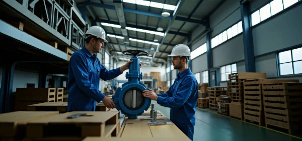
Phase 4: Finishing (Bench Work)
- Re-tapping (Back-threading): After spot facing, debris may enter the threads. We run a tap through again to clear chips and burrs, ensuring bolts screw in by hand.
- Cleaning/Grinding: Removing sticky sand from casting or oxidation scales to prepare the surface for painting.
Surface Treatment & Assembly
Large diameter valves typically undergo Epoxy Resin Spraying for corrosion resistance and aesthetic finish.
Pressure Testing
Once machined and assembled with the seat and disc, the valve undergoes rigorous testing. It must pass both the shell strength test and the sealing test. We strictly follow international protocols regarding leakage rates. Learn more about our testing limits here: Butterfly Valve Leakage Class Standards.
Phase 5: Final Inspection (QC)
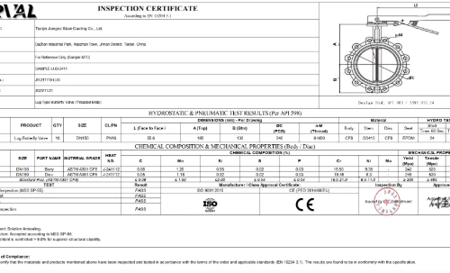
Before shipment, our Quality Control inspectors verify every dimension against the customer drawings and our 3.1 Inspection Certificate Sample requirements.
- Structural Length: Checking body thickness.
- P.C.D (Pitch Circle Diameter): verifying the accuracy of the bolt hole circle.
- Thread Go/No-Go Gauge: Ensuring thread precision.
- Symmetry & Coaxiality: Ensuring upper and lower shaft holes are concentric and lugs are symmetrical.
Need a reliable manufacturer for large diameter valves?
Contact the experts at JRVAL for precision-engineered fluid control solutions.