
 JRVAL
JRVAL Aug 06 2025
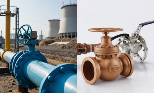
The Engineer's Guide to Butterfly Valve Leakage Classes
A standard leakage class tells you how a valve performs on day one. We'll show you what matters for long-term, reliable performance: bidirectional sealing, dynamic endurance, and reducing your total cost of ownership (TCO).
Leakage Class Comparison Chart
This table combines API 598 and ANSI/FCI 70-2, and shows where our advanced technology exceeds these baseline standards.
| Class / Standard | Allowable Leakage | Test Medium | Typical Valve Design | Common Applications | Procurement Manager's View |
|---|---|---|---|---|---|
| ANSI Class IV | 0.01% of max capacity | Air or Water | Standard Metal-Seated Valves (HPBV, TOV) | Demanding process control, high temp. | "Industry Standard Tight Shutoff" for metal seats. |
| API 598 Metal | Drops/Bubbles per minute based on size | Air or Water | All new metal-seated valves | Factory quality assurance testing. | "Factory Certified." The valve is well-made. |
| ANSI Class V | Highly restrictive leakage rate | Water | Specially engineered critical service valves | Extreme pressure/temp where minimal leakage is key. | "Elite Status." Very tight for a metal seat. |
| ANSI Class VI | Bubble Tight (a few bubbles/min) | Air or Nitrogen | Standard Resilient (Soft) Seated Valves | Utility services where tight shutoff is needed. | "Zero Visible Leakage." The common standard for soft seats. |
| API 598 Resilient | Zero Leakage (during test) | Air or Water | All new resilient seated valves | Factory quality test for seal integrity. | "Bubble Tight Certified." The seal has no defects. |
| Our Advanced Resilient Valve |
True Zero Leakage, Bidirectional | Air, Water, Gas | Innovated Soft Seat with Geometric Seal Lock | Critical isolation, high-cycle apps, pressure reversals. | "Engineered Reliability." Reduces TCO and operational risk. |
Beyond Standards: Bidirectional & Dynamic Performance
A leakage class is a static snapshot. Real-world processes are dynamic. This is where standard valves fail and where ours excel.
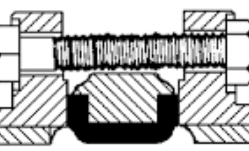
The Flaw in Standard "Bubble Tight" Valves
Most standard resilient-seated butterfly valves are "line-pressure assisted," meaning they seal tightly in one direction but can leak significantly if pressure is applied to the "wrong" side. This is a common cause of failure in systems with potential backpressure. Furthermore, their simple floating seals can extrude or wear unevenly after many cycles, degrading performance and leading to costly, unplanned shutdowns.
Our Bidirectional Zero Leakage Innovation
We've re-engineered the core of the valve. Our proprietary seat design is not reliant on line pressure. It is mechanically pre-loaded and features a geometric lock that prevents seat blowout or movement, even under full pressure reversal and high-velocity vacuum conditions. This ensures:
- True Bidirectional Sealing: Zero leakage performance at full rated pressure from either direction, guaranteed.
- Long-Term Durability: The stable seat design resists wear and tear from high cycles, extending the valve's service life and dramatically reducing your Total Cost of Ownership (TCO).
- Process Security: Eliminates a critical failure point, enhancing the safety and reliability of your entire operation.
Verified Performance & Trust
Our claims are not just words. They are backed by rigorous testing and internationally recognized certifications that matter to your business.
ISO 9001:2015
BV
CE
In-Depth Leakage Standard Specifications
For engineers and technicians requiring precise data, this section provides detailed tables from major international standards: API 598, ANSI/FCI 70-2, EN 12266-1, and ISO 5208.
ANSI/FCI 70-2 (Supersedes ANSI B16.104)
This is the primary North American standard for control valve seat leakage. It defines six leakage classes, from Class I (referential) to Class VI (bubble-tight). Our summary table at the top of the page simplifies this, but the full testing requirements are detailed below.
| Class Designation | Maximum Allowable Leakage | Test Medium | Test Pressure | Testing Procedures Required for Establishing Rating |
|---|---|---|---|---|
| CLASS I | (See note in last column) | - | - | No test required. A design classification only. Intended for open/close applications where seat leakage is not a consideration. |
| CLASS II | 0.5% of rated valve capacity | Air or water | 45-60 psig or max operating differential, whichever is lower | Pressure applied to valve inlet with outlet open to atmosphere. Use appropriate measuring device for flow. |
| CLASS III | 0.1% of rated valve capacity | Air or water | 45-60 psig or max operating differential, whichever is lower | Pressure applied to valve inlet with outlet open to atmosphere. Use appropriate measuring device for flow. |
| CLASS IV | 0.01% of rated valve capacity | Air or water | 45-60 psig or max operating differential, whichever is lower | Pressure applied to valve inlet with outlet open to atmosphere. This is considered the industry standard for metal-seated valves. |
| CLASS V | 5 x 10⁻⁴ ml per minute per inch of port diameter per psi differential (0.0005 ml/min/inch/psi) | Water | Max service pressure drop across valve plug, not to exceed ANSI body rating | Pressure applied to inlet after filling entire body cavity. Use specified actuator thrust. Measure leakage with suitable device. |
| CLASS VI | Not to exceed amounts in the table below (based on port diameter) | Air or nitrogen | 50 psig or max rated differential pressure across valve plug, whichever is lower | Actuator should be adjusted to operating conditions. Allow time for leakage flow to stabilize before measuring. Known as "bubble-tight". |
ANSI/FCI 70-2 Class VI Leakage Rates (Bubble Test) - Exhaustive Table
| Nominal Port Diameter (Inches) | Nominal Port Diameter (mm) | Allowable Leakage (ml per Minute) | Allowable Leakage (Bubbles per Minute*) |
|---|---|---|---|
| 1 | 25 | 0.15 | 1 |
| 1.5 | 38 | 0.30 | 2 |
| 2 | 51 | 0.45 | 3 |
| 2.5 | 64 | 0.60 | 4 |
| 3 | 76 | 0.90 | 6 |
| 4 | 102 | 1.70 | 11 |
| 6 | 152 | 4.00 | 27 |
| 8 | 203 | 6.75 | 45 |
| 10 | 254 | 9.00 | 63 |
| 12 | 305 | 11.5 | 81 |
| 14 | 356 | 14.0 | 98 |
| 16 | 406 | 17.5 | 123 |
| 18 | 457 | 21.0 | 147 |
| 20 | 508 | 25.0 | 175 |
| 24 | 610 | 36.0 | 252 |
| 30 | 762 | 56.0 | 392 |
| 36 | 914 | 81.0 | 567 |
| 48 | 1219 | 144.0 | 1008 |
| 60 | 1524 | 225 | ~1575 |
| 72 | 1829 | 324 | ~2268 |
| 80 | 2032 | 400 | ~2800 |
| 96 | 2438 | 576 | ~4032 |
| 120 | 3048 | 900 | ~6300 |
| 140 | 3556 | 1225 | ~8575 |
| 160 | 4064 | 1600 | ~11200 |
|
*Bubbles per minute as tabulated are a suggested alternative based on a suitable calibrated measuring device, in this case a 0.25-inch OD x 0.032-inch wall tube submerged in water to a depth of from 1/8 to 1/4 inch. The bubble count is an approximation. Note on Extended Data: Values for sizes 14" to 48" are based on widely accepted industry data extensions of the standard. Values for sizes 60" (DN1500) and larger are highlighted as they represent engineering extrapolation based on the established relationship between diameter and leakage rate (approximated by L(ml/min) ≈ (D"/4)²). These extrapolated values are for engineering reference only and must be confirmed with the manufacturer for critical applications. |
|||
EN 12266-1: European Standard
This European standard specifies tests, test procedures, and acceptance criteria for industrial valves. "Rate A" represents zero detectable leakage, which is equivalent to our advanced bidirectional soft-seat technology and API 598 zero leakage. The formulas below (where DN is Nominal Diameter in mm) are used to calculate allowable leakage for various rates.
| Leakage Rate | Maximum allowable leakage for seat test (Test P12) |
|---|---|
| Rate A | No visually detectable leakage for the duration of the test. |
| Rate B | For liquids: 0.01 × DN (in mm³/s) For gases: 0.3 × DN (in mm³/s) |
| Rate C | For liquids: 0.03 × DN (in mm³/s) For gases: 3.0 × DN (in mm³/s) |
| Rate D | For liquids: 0.1 × DN (in mm³/s) For gases: 30 × DN (in mm³/s) |
| Rate E | For liquids: 0.3 × DN (in mm³/s) For gases: 300 × DN (in mm³/s) |
| Rate F | For liquids: 1.0 × DN (in mm³/s) For gases: 3000 × DN (in mm³/s) |
| Rate G | For liquids: 2.0 × DN (in mm³/s) For gases: 6000 × DN (in mm³/s) |
EN 12266-1 Calculated Leakage Rate Examples (mm³/s)
| DN | Rate B | Rate C | Rate D | Rate E | Rate F | Rate G | ||||||
|---|---|---|---|---|---|---|---|---|---|---|---|---|
| Liquid | Gas | Liquid | Gas | Liquid | Gas | Liquid | Gas | Liquid | Gas | Liquid | Gas | |
| 50 | 0.5 | 15 | 1.5 | 150 | 5 | 1,500 | 15 | 15,000 | 50 | 150,000 | 100 | 300,000 |
| 100 | 1 | 30 | 3 | 300 | 10 | 3,000 | 30 | 30,000 | 100 | 300,000 | 200 | 600,000 |
| 150 | 1.5 | 45 | 4.5 | 450 | 15 | 4,500 | 45 | 45,000 | 150 | 450,000 | 300 | 900,000 |
| 200 | 2 | 60 | 6 | 600 | 20 | 6,000 | 60 | 60,000 | 200 | 600,000 | 400 | 1,200,000 |
| 300 | 3 | 90 | 9 | 900 | 30 | 9,000 | 90 | 90,000 | 300 | 900,000 | 600 | 1,800,000 |
| 400 | 4 | 120 | 12 | 1,200 | 40 | 12,000 | 120 | 120,000 | 400 | 1,200,000 | 800 | 2,400,000 |
| 500 | 5 | 150 | 15 | 1,500 | 50 | 15,000 | 150 | 150,000 | 500 | 1,500,000 | 1,000 | 3,000,000 |
| 600 | 6 | 180 | 18 | 1,800 | 60 | 18,000 | 180 | 180,000 | 600 | 1,800,000 | 1,200 | 3,600,000 |
| 800 | 8 | 240 | 24 | 2,400 | 80 | 24,000 | 240 | 240,000 | 800 | 2,400,000 | 1,600 | 4,800,000 |
| 1000 | 10 | 300 | 30 | 3,000 | 100 | 30,000 | 300 | 300,000 | 1,000 | 3,000,000 | 2,000 | 6,000,000 |
| 1200 | 12 | 360 | 36 | 3,600 | 120 | 36,000 | 360 | 360,000 | 1,200 | 3,600,000 | 2,400 | 7,200,000 |
| 1500 | 15 | 450 | 45 | 4,500 | 150 | 45,000 | 450 | 450,000 | 1,500 | 4,500,000 | 3,000 | 9,000,000 |
| 2000 | 20 | 600 | 60 | 6,000 | 200 | 60,000 | 600 | 600,000 | 2,000 | 6,000,000 | 4,000 | 12,000,000 |
| 2500 | 25 | 750 | 75 | 7,500 | 250 | 75,000 | 750 | 750,000 | 2,500 | 7,500,000 | 5,000 | 15,000,000 |
| 3000 | 30 | 900 | 90 | 9,000 | 300 | 90,000 | 900 | 900,000 | 3,000 | 9,000,000 | 6,000 | 18,000,000 |
| 4000 | 40 | 1,200 | 120 | 12,000 | 400 | 120,000 | 1,200 | 1,200,000 | 4,000 | 12,000,000 | 8,000 | 24,000,000 |
|
Note on Calculated Values: All values in this table are mathematically derived from the formulas specified in EN 12266-1. Rate D is often considered roughly equivalent to ANSI Class IV for metal-seated valves. Values for sizes DN1500 and larger are highlighted to indicate they are based on standard formula application to large-scale projects, and final design parameters should be confirmed with the manufacturer. |
||||||||||||
API 598: The Global Standard for Valve Inspection and Testing
The American Petroleum Institute (API) Standard 598 covers the inspection, examination, and testing requirements for gate, globe, check, ball, plug, and butterfly valves. It is a benchmark for quality assurance. "Zero leakage" is permitted for resilient-seated valves under this standard during the specified test duration. For metal-seated valves, a small, defined amount of leakage is permitted.
API 598 Allowable Leakage for Metal-Seated Valves (Excluding Check Valves)
| Valve Size NPS (inches) | Valve Size DN (mm) | Closure Test (Liquid) | Closure Test (Gas) | ||
|---|---|---|---|---|---|
| Drops per minute | ml per minute | Bubbles per minute | ml per minute | ||
| ≤ 2 | ≤ 50 | 0 | 0 | 0 | 0 |
| 2 ½ – 6 | 65–150 | 12 | 0.6 | 24 | 1.2 |
| 8–12 | 200–300 | 24 | 1.2 | 48 | 2.4 |
| 14–24 | 350–600 | 40 | 2.0 | 80 | 4.0 |
| ≥ 26 | ≥ 650 | 2 drops / min / inch | 0.1 ml / min / inch | 4 bubbles / min / inch | 0.2 ml / min / inch |
|
Test Conditions: Liquid test at 1.1x max working pressure. Gas test at 80 psig. Test duration varies by size. For sizes ≥ 26", the leakage rate is calculated per inch of nominal pipe size. For example, a 30" valve would be allowed 60 drops/min (liquid) or 120 bubbles/min (gas). |
|||||
ISO 5208: International Standard
ISO 5208 is an international standard for industrial valve pressure testing, acceptance criteria, and procedures. It is harmonized with EN 12266-1, and its leakage rates are very similar. Rate A signifies no visible leakage.
| Leakage Rate | Maximum allowable seat leakage |
|---|---|
| Rate A | No visually detectable leakage for the duration of the test. |
| Rate AA | For liquids: 0.0003 × DN (in mm³/s) For gases: 0.03 × DN (in mm³/s) |
| Rate B | For liquids: 0.01 × DN (in mm³/s) For gases: 0.3 × DN (in mm³/s) |
| Rate C | For liquids: 0.03 × DN (in mm³/s) For gases: 3.0 × DN (in mm³/s) |
| Rate CC | For liquids: 0.06 × DN (in mm³/s) For gases: 6.0 × DN (in mm³/s) |
| Rate D | For liquids: 0.1 × DN (in mm³/s) For gases: 30 × DN (in mm³/s) |
| Rate E | For liquids: 0.3 × DN (in mm³/s) For gases: 300 × DN (in mm³/s) |
| Rate F | For liquids: 1.0 × DN (in mm³/s) For gases: 3000 × DN (in mm³/s) |
| Rate G | For liquids: 2.0 × DN (in mm³/s) For gases: 6000 × DN (in mm³/s) |
ISO 5208 Calculated Leakage Rate Examples (Gas, mm³/s)
| DN | Rate AA (Gas) | Rate B (Gas) | Rate C (Gas) | Rate D (Gas) |
|---|---|---|---|---|
| 50 | 1.5 | 15 | 150 | 1,500 |
| 100 | 3 | 30 | 300 | 3,000 |
| 200 | 6 | 60 | 600 | 6,000 |
| 300 | 9 | 90 | 900 | 9,000 |
| 400 | 12 | 120 | 1,200 | 12,000 |
| 600 | 18 | 180 | 1,800 | 18,000 |
| 800 | 24 | 240 | 2,400 | 24,000 |
| 1000 | 30 | 300 | 3,000 | 30,000 |
| 1500 | 45 | 450 | 4,500 | 45,000 |
| 2000 | 60 | 600 | 6,000 | 60,000 |
|
Note on Calculated Values: This table shows a sample of calculated gas leakage rates for various ISO 5208 classes. The harmonization with EN 12266-1 means the logic and calculations are directly comparable. Rate D is often considered the equivalent of ANSI Class IV. |
||||
Valves Engineered for Your Leakage Requirements
Connect the standard to the solution. Find the right valve based on the performance level your application demands.
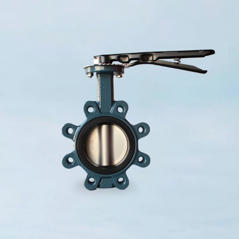
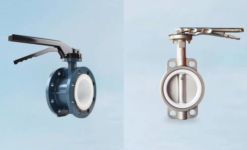
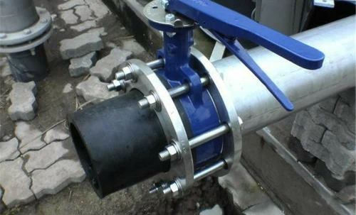
Standard Resilient Seated Butterfly Valve
- Leakage Class: ANSI Class VI / API 598
- Best For: General utilities, water/wastewater, HVAC.
- Key Feature: Cost-effective bubble-tight shutoff in preferred direction.
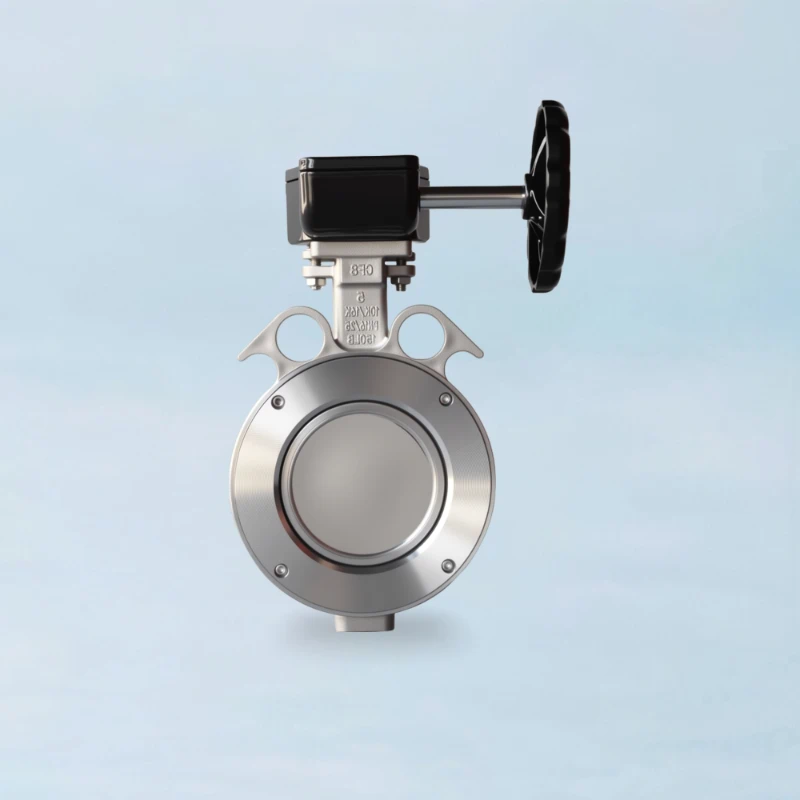
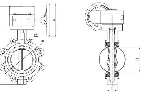
High-Performance Butterfly Valve (HPBV)
- Leakage Class: ANSI Class IV / V (Metal Seat)
- Best For: High temperature, high pressure, chemical processing.
- Key Feature: Tight shutoff in demanding services where soft seats are not suitable.
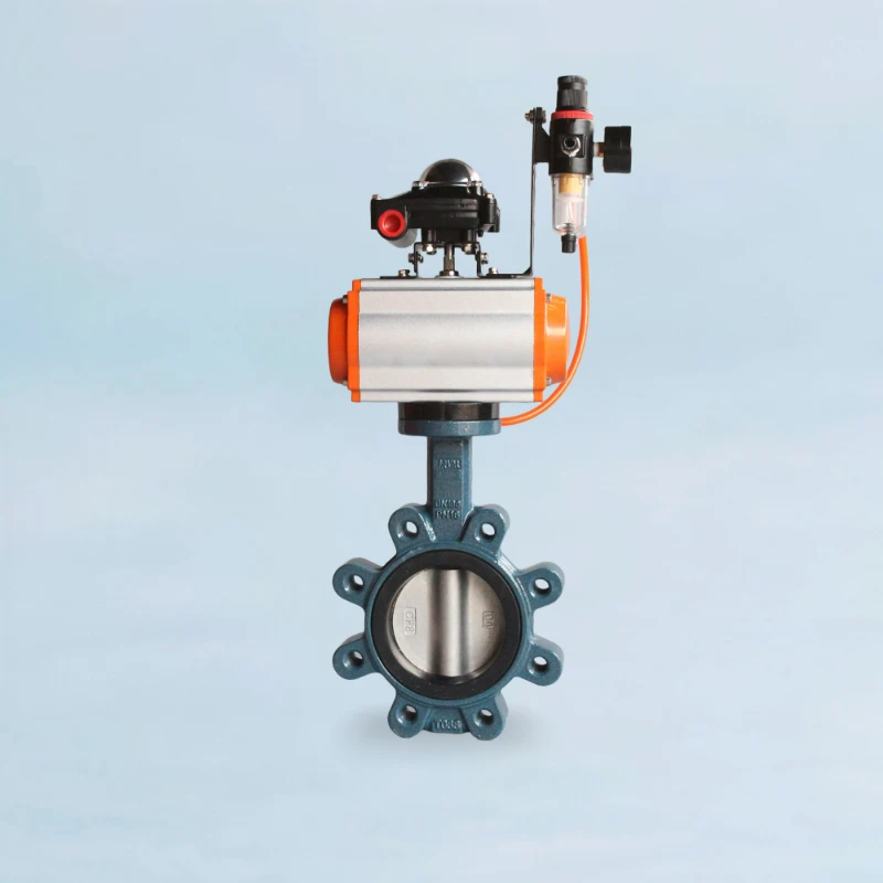
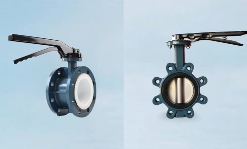
Advanced Bidirectional Zero-Leakage Valve
- Leakage Class: Exceeds API 598 & ANSI Class VI
- Best For: Critical isolation, high cycles, systems with backpressure.
- Key Feature: True zero leakage in both directions, guaranteed. Reduces TCO.
Frequently Asked Questions
What is the difference between API 598 "Zero Leakage" and ANSI Class VI "Bubble Tight"?
While both imply excellent sealing, there's a technical distinction. API 598 for resilient seats allows absolutely NO leakage during the test. ANSI Class VI allows a very small, specified number of bubbles per minute based on valve size. Therefore, API 598 is technically a more stringent standard for resilient-seated valves. Our advanced valves meet and exceed the API 598 standard.
Why should I care about bidirectional sealing? My flow is only one way.
Processes can be unpredictable. A pump trip, downstream valve closure, or system upset can cause sudden backpressure. In a standard valve, this can cause the seal to unseat, leading to leakage. A true bidirectional valve provides insurance against these events, protecting your process, equipment, and personnel. It's a critical feature for enhancing system reliability and safety.
Is a metal-seated valve (Class IV) good enough for isolation?
It depends on your definition of "isolation." ANSI Class IV allows a small, permissible leakage rate. For many process control applications, this is acceptable. However, for critical applications requiring absolute shutoff for safety or to prevent product contamination, a zero-leakage valve (like our advanced resilient-seated design) is required. Always choose based on the consequence of leakage.
Need Help with Your Valve?
Our engineers can ensure you get the right performance for your application.